Rasp bar and support

a technology of rasp bar and support, which is applied in the field of rotary threshing systems, can solve the problems of rasp bar wear and retention during operation, significant damage to the rotor and rotor cage, and failure of rasp bar, so as to improve material metallurgy, improve attachment stability, and accurately translate the effect of applied toque into clamp load

Active Publication Date: 2012-08-23
BLUE LEAF I P INC
View PDF6 Cites 18 Cited by
  • Summary
  • Abstract
  • Description
  • Claims
  • Application Information

AI Technical Summary

Benefits of technology

[0010]An advantage of the present invention is that it provides for a rasp bar assembly design that has improved attachment stability to the rasp bar support, thereby protecting the rotor and rotor cage from damage.
[0011]Another advantage of the present invention is that it provides for a rasp bar assembly having a more accurate translation of applied toque into clamp load.
[0012]Another advantage of the present invention is that it provides for a rasp bar assembly having improved material metallurgy.
[0013]Other features and advantages of the present invention will be apparent from the following more detailed description of the preferred embodiment, taken in conjunction with the accompanying drawings which illustrate, by way of example, the principles of the invention.

Problems solved by technology

First, rough bolting surfaces on the rasp bars may cause an inconsistent translation of applied torque into effective clamp loading of the rasp bar to the rasp bar support that may lead to a rasp bar failure, which may significantly damage the rotor and rotor cage.
Second, rasp bar wear and retention during operation has become an issue due to increased rotor capacity and / or material flow.
In particular, when impacted by harvested material such as corn, or by foreign material such as soil and / or rocks, the rasp bar may rotate about the rasp bar support bracket causing lost bolt tension and clamp load, leading to rasp bar retention failure.

Method used


Image

  • Rasp bar and support
  • Rasp bar and support
  • Rasp bar and support

Examples


Embodiment Construction

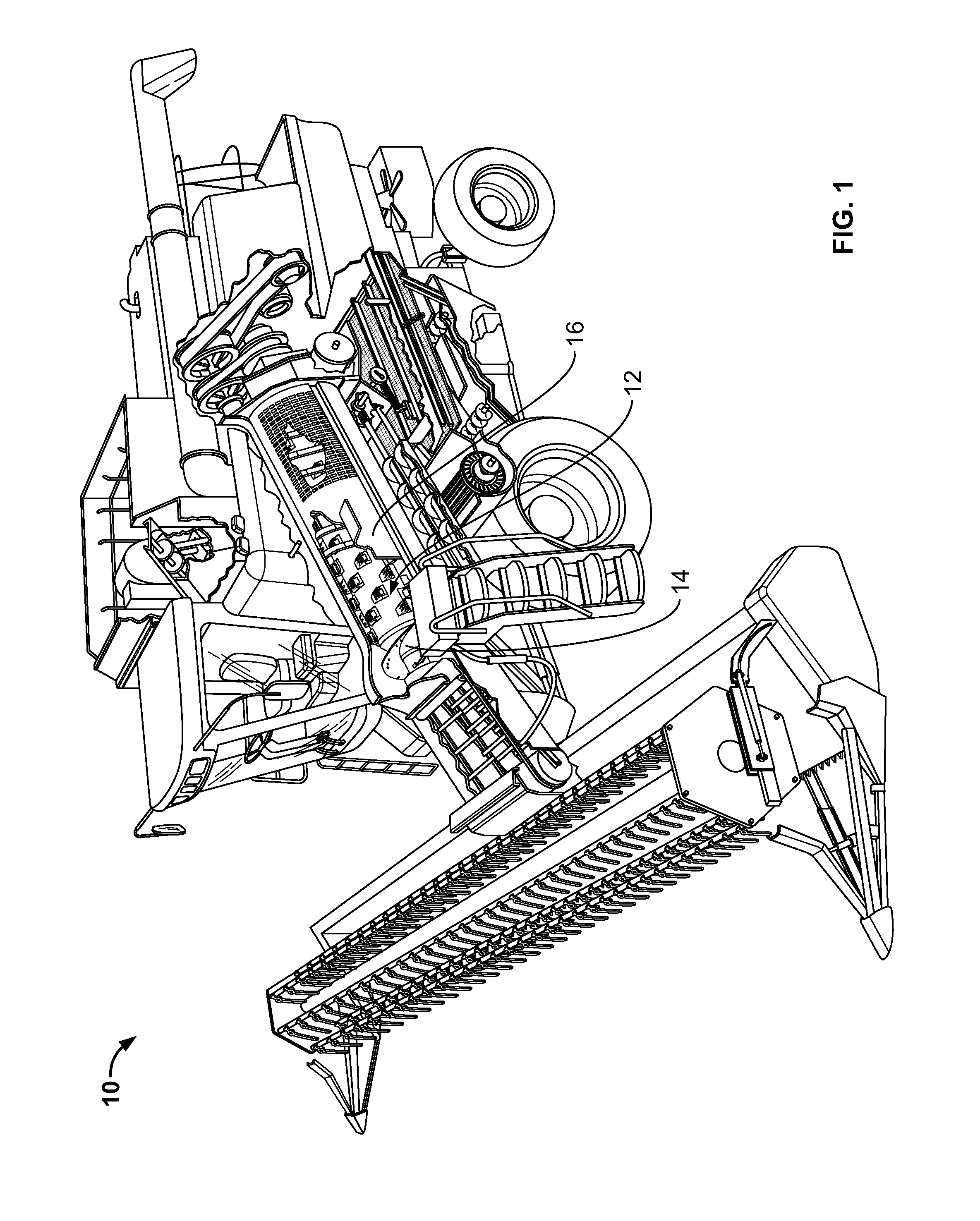
[0027]FIG. 1 depicts an embodiment of an agricultural combine 10 according to the invention. The agricultural combine 10 includes a rotary threshing system 12 having a threshing rotor 14 in a rotor cage 16. In another embodiment, the agricultural combine 10 may have two or more threshing rotors 14. Agricultural combine 10 is representative of an axial flow-type combine including one or two fore and aft extending threshing rotors, but it should be understood that it is contemplated that the invention can likewise be used with rotors of other types of combines, including, but not limited to, conventional types wherein one or more rotors of the invention will be mounted in a transverse orientation within a body of the combine.

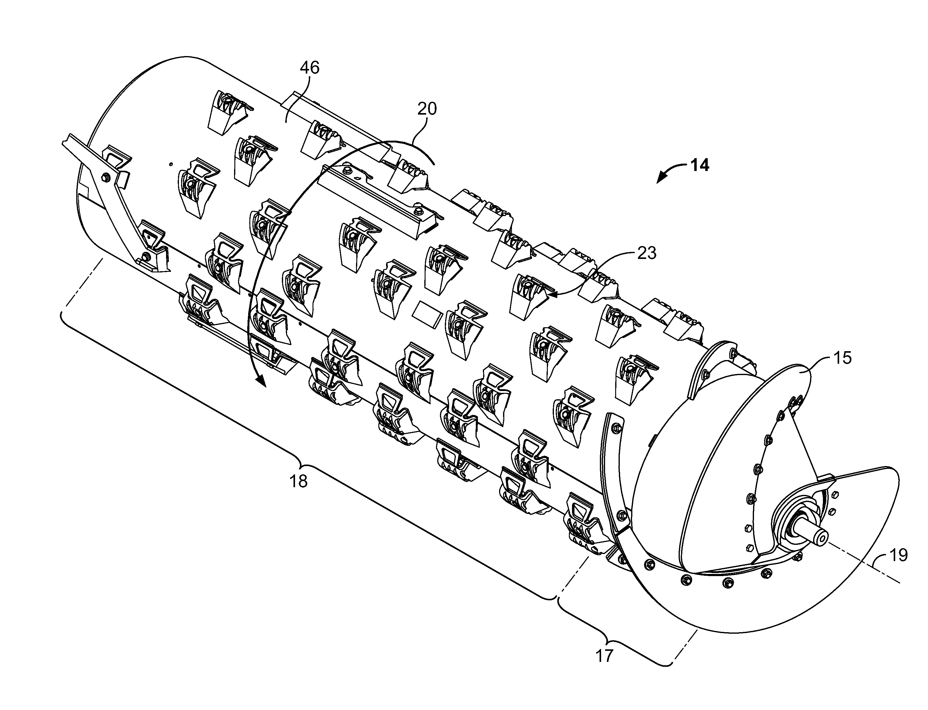
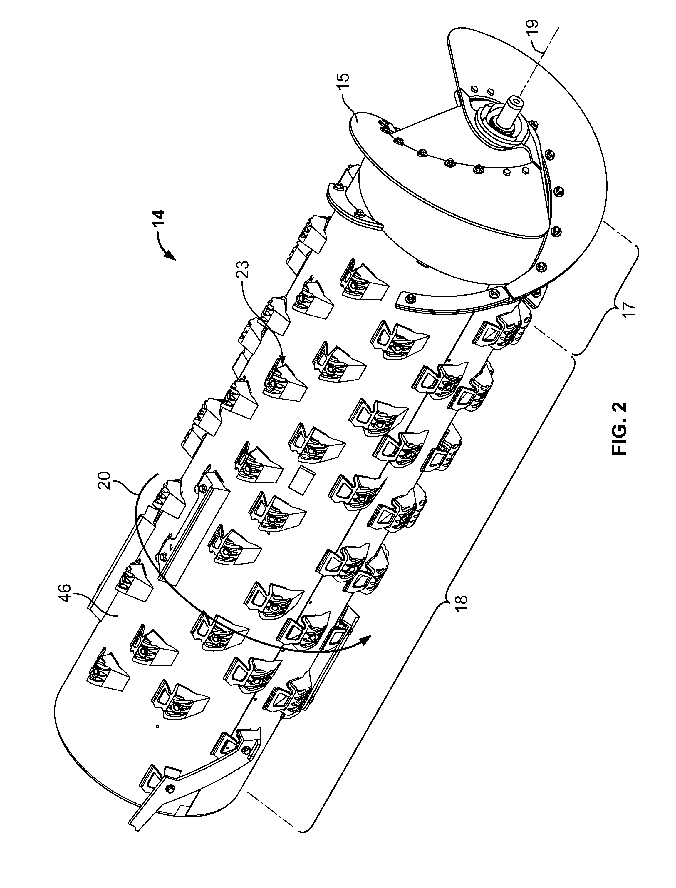
[0028]FIG. 2 shows a threshing rotor 14 according to an embodiment of the invention. As can be seen in FIG. 2, the threshing rotor 14 includes an auger flight 15 at an in-feed portion 17 to transfer crop material to a threshing portion 18. Threshing rotor 14 inclu...


PUM


Abstract

A rasp bar assembly is disclosed that includes a rasp bar having a plurality of rotation stops that contact the rasp bar mount. The plurality of rotation stops stabilize the rasp bar upon the rasp bar mount and prevent the rasp bar from rotating from its assembled position.

Description

FIELD OF THE INVENTION[0001]The present invention is directed to rotary threshing systems for agricultural combines and, more particularly, to rasp bar assemblies for mounting on threshing rotors in axial flow-type combines.BACKGROUND OF THE INVENTION[0002]Many agricultural combines use a rotary threshing and / or separating system. The system typically includes at least one rotor drivingly rotated within a rotor housing or cage including a perforated concave spaced radially outwardly thereof. The rotor will often have a frusto-conical inlet end having a helical flight or flights there around for conveying a flow of crop material into a space between the rotor and the rotor cage. The main body of the rotor will typically have an array or layout of threshing elements, typically rasp bars, which protrude radially outwardly into the space for conveying a mat of the crop material along a helical path through the space. Rasp bars cooperate with the rotor housing to separate larger componen...

Claims


Application Information

Patent Timeline
Patent Type & Authority Applications(United States)
IPC IPC(8): A01F12/18A01F12/22
CPCA01F12/22
Inventor MURRAY, CRAIG W.TANIS, DALE R.DOBBINS, DAVID V.WILSON, RANDALL L.
Owner BLUE LEAF I P INC
Why Eureka
Try Eureka