Pfo closing device

a technology of a closing device and a foramen ovale, which is applied in the field of medical devices, can solve the problems of stroke or migraine, difficult dosage management, and inability to stop bleeding easily, and achieve the effects of speeding up the procedure, facilitating the procedure, and being convenient to us

Active Publication Date: 2012-08-23
TERUMO KK
View PDF0 Cites 0 Cited by
  • Summary
  • Abstract
  • Description
  • Claims
  • Application Information

AI Technical Summary

Benefits of technology

[0016]Since substantially the needle part and the clamping member or both of them together with holding means are only stored in the catheter, the present device is simple in configuration, which facilitates the procedure.
[0017]The present device, when having the holding means, holds the tissues composed of the SP and the SS at the time of puncturing. Therefore, the puncturing operation or the joining operation can be performed accurately and assuredly, whereby the procedure can be made to be accurate, speedy and easy.
[0018]Particularly where the present device has holding means including a positioning part for positioning the needle part relative to the PFO and a holding part for holding the SP so that the SP cannot be retracted relative to the needle part, the operation of positioning the needle part and the operation of holding the SP can be carried out in an undivided manner. Therefore, even a thin-walled SP can be punctured at a predetermined position, without breakage or damage. This enhances largely the safety and easiness of the procedure, and the procedure can be carried out accurately and speedily. Particularly, the positioning and holding means ensures that the positioning of the needle part and the holding of the SP can be performed by only operating the operating member to move axially forwards or rearwards, so that the convenience or facility of the procedure is enhanced.
[0019]Preferably, the positioning and holding means has a main tube passed through the catheter and capable of being operated externally, an operating member provided in the main tube so as to be movable axially forwards and rearwards, is protruded from the distal end of the main tube, an intermediate sleeve body and a tip sleeve body are provided coaxially with the operating member, and a contact member brought into contact with the tip sleeve body by pulling the operating member is provided at a distal end portion of the operating member. The tip sleeve body and the intermediate sleeve body are connected to each other by a first elastic wire member, and the intermediate sleeve body and the tip sleeve body are connected to each other by a second elastic wire member deformable more easily than the first elastic wire member. The second elastic wire member is curved outwards by pulling the operating member to thereby function as the positioning part making springy contact with the inner edge of the PFO. The first elastic wire member between the tip sleeve body and the contact member and the intermediate sleeve body is curved by further pulling the operating member to thereby function as a holding part for holding the SP by the tip sleeve body and the contact member. This configuration helps ensure that the positioning and the holding of the SP can be performed more assuredly, thereby enhancing the safety, facility, accurateness, and speediness of the procedure. Preferably, the positioning and holding means has a structure in which a main tube capable of being, operated externally protrudes from the distal end of the catheter, an operating member movable axially forwards and rearwards is provided in the main tube, and an elastic second sleeve body is disposed at a distal end portion of the main tube. A positioning piece formed at a proximal portion of the second sleeve body is curved outwards by pulling, by the operating member, the second sleeve body protruded from the main tube, to thereby function as the positioning part making springy contact with the inner edge of the PFO, and a distal end portion of the second sleeve body is curved by further pulling the operating member to thereby function as a holding part for holding the SP from the side of the left atrium of heart. This ensures not only the safety, facility, accurateness, and speediness of the procedure but also a simpler configuration of the PFO closing device.
[0020]Preferably, the positioning and holding means has a positioning part including a pair of elastic wire members protruding from a distal end portion of the catheter so as to be opened wider, and a holding part for holding the SP in a non-retractable manner by a projected part formed at the center of an M shape into which distal end portions of the elastic wire members are deformed. This helps ensure not only the safety, facility, accurateness, and speediness of the procedure but also a simpler configuration of the PFO closing device and inexpensiveness of the device.
[0021]The positioning and holding means has a main tube passing through the catheter and capable of being operated externally, an operating member provided in the main tube so as to be movable axially forwards and rearwards is protruded from the distal end of the main tube, an intermediate sleeve body and a tip sleeve body are provided coaxially with the operating member, and a contact member brought into contact with the tip sleeve body by pulling the operating member is provided at a distal end portion of the operating member; the main tube and the intermediate sleeve body—are connected to each other by a first elastic wire member, the intermediate sleeve body and the tip sleeve body are connected to each other by a second elastic wire member and a third elastic wire member projectingly deformable more easily than the second elastic wire member; the first elastic wire member is curved outwards by pulling the operating member to thereby function as the positioning part making springy contact with the inner edge of the foramen ovale, and by further pulling the operating member, the second elastic wire member is curved so that the tip sleeve body and the contact member function as a holding part for holding the septum primum, and the third elastic wire member is curved outwards to thereby function as a crease smoothing part for smoothing out creases present in the septum primum. This also ensures not only the safety, facility, accurateness, and speediness of the procedure but also a simpler configuration of the PFO closing device.

Problems solved by technology

If thrombi are contained in the blood in this case, the thrombi are transferred from the vein side to the artery side, and flow from the left atrium of heart into the left ventricle, then into the aorta and into the brain, possibly causing a stroke or migraine.
Pharmacotherapy is the treatment which should be selected first, but it can be difficult to manage the dosage, and bleeding may not cease easily during the dosage.
The conventional devices, however, are based on clamping the SP and the SS by use of a disk-like membrane or anchor member for closing the defect, and they are left indwelling in the patient's body.
Particularly, when a thrombus deposits on the disk-like membrane on the side of the left atrium of the heart, it may flow downstream to cause stroke, or may break the SP which is small in wall thickness.

Method used


Image

  • Pfo closing device
  • Pfo closing device
  • Pfo closing device

Examples


first embodiment

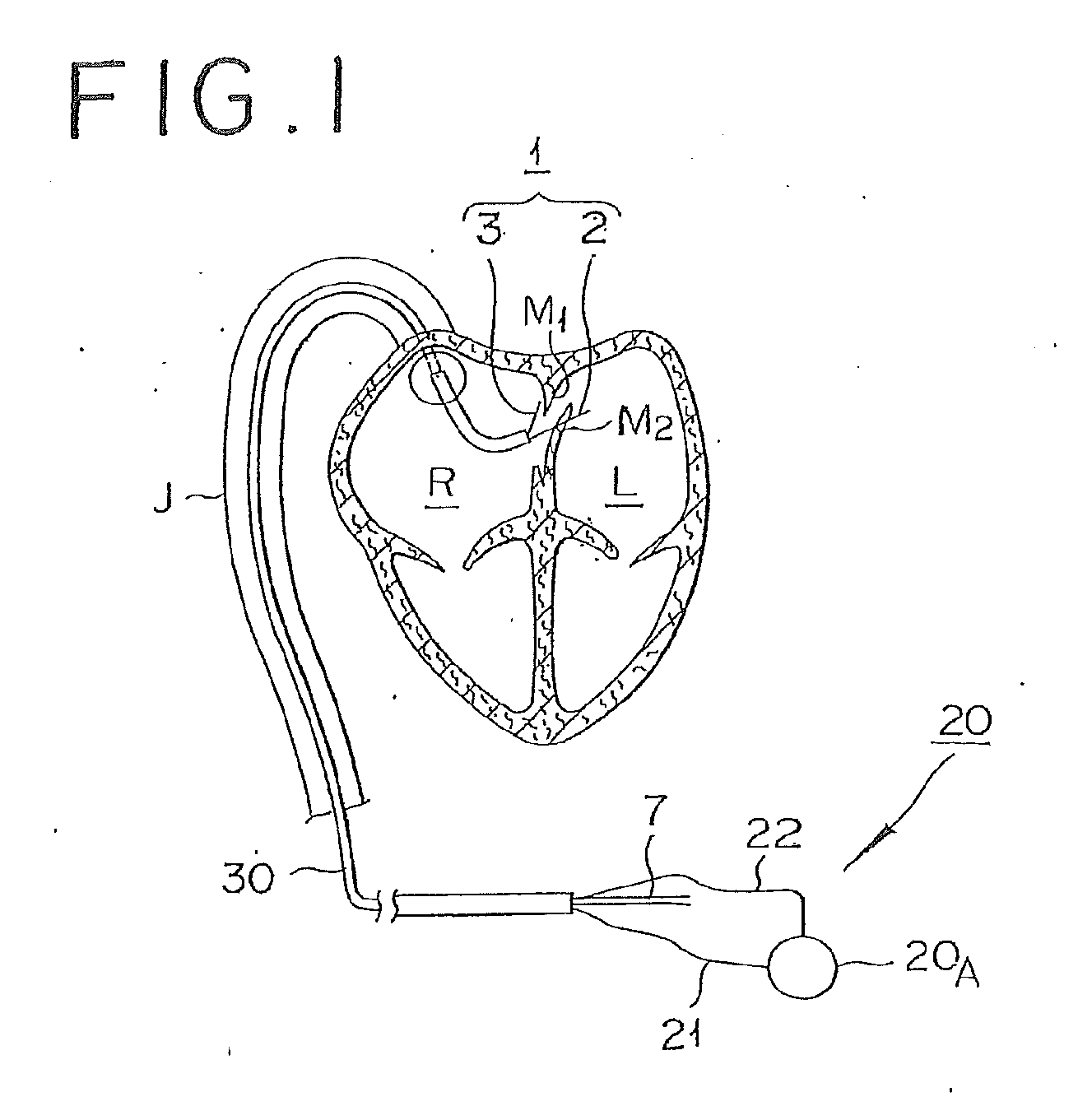
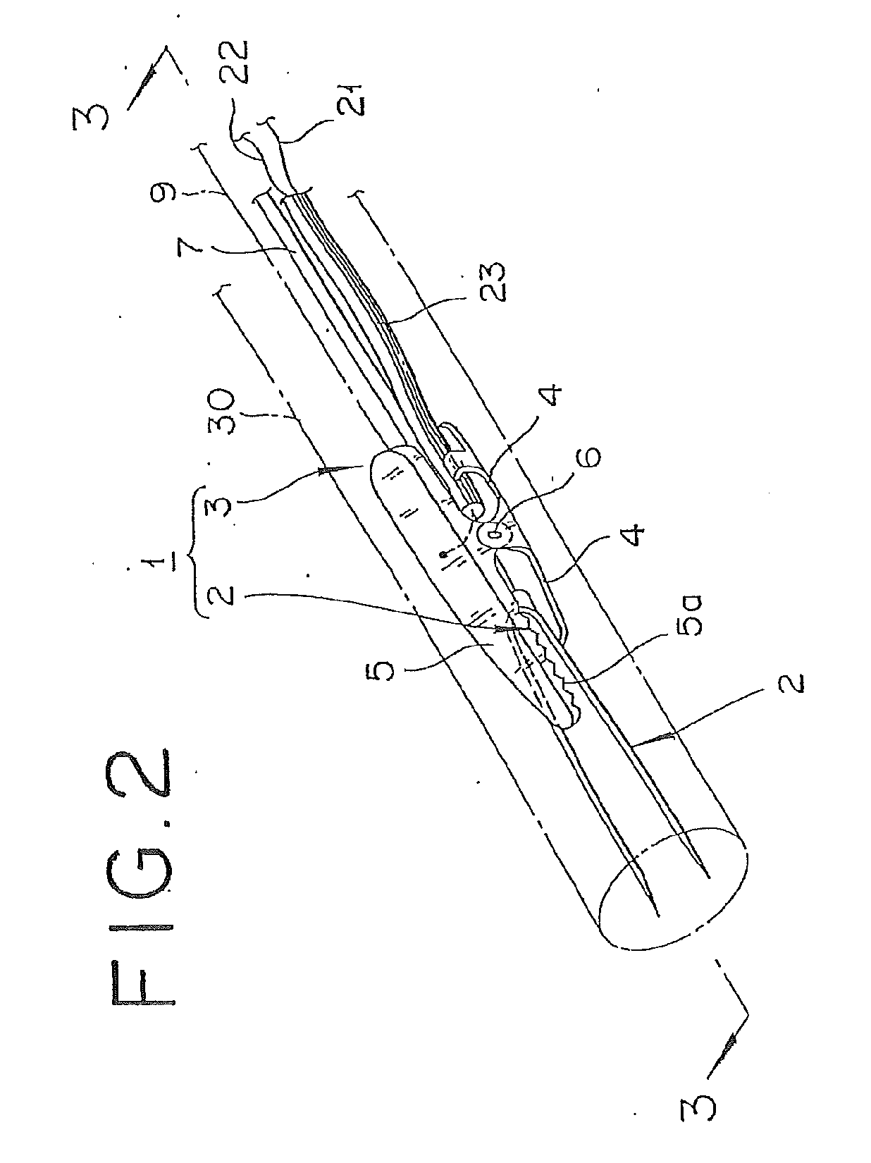
[0056]the PFO closing device disclosed here is described with reference to FIGS. 1-3. As shown in FIG. 1, the PFO closing device according to this embodiment generally includes clamping means 1 for clamping a septum primum (hereinafter referred to as SP M2) and a septum secundum (hereinafter referred to as SS M1), and energy-supplying means 20 for supplying energy to join the tissues clamped by the clamping means 1. The clamping means 1 is movably positioned in the distal end (tip) of an elongated member 30, which includes a lumen, in a manner allowing the clamping means 1 to protrude out of and retract into (e.g., be movable forward and rearward) the elongated member. In the illustrated embodiment, the elongated hollow member (elongated lumen-possessing member) is a percutaneous catheter 30. In use, the clamping means 1, while being wholly stored or positioned in the catheter 30, is inserted in an inferior vena cava J. Then, in performing the procedure, the clamping means 1 protrud...

second embodiment

[0075]The PFO closing device according to this second embodiment is preferable from the standpoint that the clamping means 1 can be stored or positioned in a catheter 30 in a more compact manner.

[0076]As shown in FIG. 6, the PFO closing device in this embodiment generally includes a guiding catheter 31, the catheter 30, the clamping means 1, positioning means 40, and energy supplying means similar to the energy supply means of the first embodiment. The guiding catheter 31 is provided at an outermost portion of the device. The catheter 30 is positioned in the guiding catheter 31. The clamping means 1 includes the needle part 2 positionally fixedly provided inside the catheter 30 to protrude from the distal end of the catheter 30, and a clamping member 3A turnably provided in the outside of the distal end portion of the catheter 30. The positioning means 40 is for positioning the needle part 2 at the center of the PFO 0.

[0077]As shown in FIG. 7, the needle part 2 constituting one side...

fourth embodiment

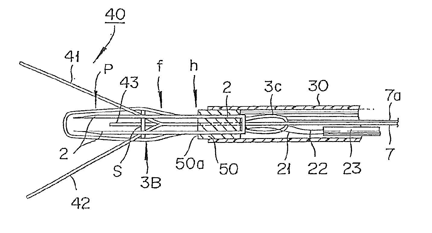
[0107]the PFO closing device is shown in FIGS. 20-24. In the description which follows, features of this embodiment of the closing device which are the same as those associated with the embodiments described above are identified by the same reference numerals, and a detailed description of such features is not repeated.

[0108]This fourth embodiment is basically the same as the third embodiment, except that the positioning means 40 and the gripping member (clamping member) 3B are somewhat different. As shown in FIGS. 20 and 21, a support 50 is provided with six lumens. The elongated members of the needle part 2 pass through first and second lumens LI, L2 of the support and are positionally fixedly attached to the support 50. The spaced apart legs of the clamping member 3B pass through the third and fourth lumens L3, L4 of the support 50, and the positioning means 40 passes through fifth and sixth lumens L5, L6 located at intermediate positions between the lumens L1, L2 and L3, L4.

[010...


PUM


Abstract

A PFO closing device for bringing the septum primum and the septum secundum into contact with each other and joining them together includes a clamping mechanism and energy supplying device. The clamping mechanism includes a needle part for puncturing the septum primum, and a clamping member for cooperating with the needle part in clamping therebetween tissue of the septum primum and the septum secundum. The energy supplying device supplies energy for joining the tissues clamped by the needle part and the clamping member. The clamping mechanism is mounted in a catheter so as to be protrudable from and retractable into the catheter.

Description

[0001]This application is a continuation of application Ser. No. 12 / 230,090 filed Aug. 22, 2008, which is a continuation of International Application No. PCT / JP2007 / 053977 filed on Feb. 23, 2007, the entire content of both of which is incorporated herein by reference. This application also claims priority under 35 U.S.C. §119(a) to Japanese Application No. 2006-047636 filed on Feb. 24, 2006, the entire content of which is also incorporated herein by reference.TECHNOLOGICAL FIELD[0002]The present invention generally relates to a medical device. More specifically, the invention pertains to a patent foramen ovale (PFO) closing device for closing a PFO in a person's heart.BACKGROUND DISCUSSION[0003]Recently, patent foramen ovale (hereinafter referred to as PFO) has been identified as a cardiac factor in strokes and migraines. The PFO is a symptom in which the oval foramen (foramen ovale) for shortcircuiting blood between the left and right sides in the heart in the fetal period of a per...

Claims


Application Information

Patent Timeline
Patent Type & Authority Applications(United States)
IPC IPC(8): A61B17/03
CPCA61B18/1445A61B18/1492A61B2018/1432A61B2017/00575A61B2017/2945A61B2017/00243A61B17/11A61B17/12A61B18/14
Inventor KATO, YUKITOSHI
Owner TERUMO KK
Why Eureka
Try Eureka