Charge bypass system for engine start

a technology of bypass system and engine, which is applied in the direction of engine starter, machine/engine, servomotor, etc., can solve the problems of difficult cranking of the engine, difficulty in starting the conventional engine, and difficulty in cranking the engine, so as to reduce the parasitic load of the engine, reduce the pressure of the charge system, and reduce the effect of parasitic load

Active Publication Date: 2012-08-30
DEERE & CO
View PDF2 Cites 3 Cited by
  • Summary
  • Abstract
  • Description
  • Claims
  • Application Information

AI Technical Summary

Benefits of technology

[0015]In the present disclosure, the bypass system provides a means for reducing the parasitic load on the engine. This is particularly true when fluid temperatures are at or below a threshold temperature and the engine has not yet started. Although the fluid viscosity is higher than during normal operation, the pressure in the charge system can be reduced by the bypass system and therefore reduce the parasitic load. This makes it easier to start the engine in colder temperatures.
[0016]Another advantage is once the engine is started, the bypass system can be deactivated so that the charge system returns to normal operation. In other words, the bypass system can be activated to assist with engine start in cold temperatures, but once the engine starts, the bypass system can be deactivated. This enhanced controllability function of the bypass system overcomes many limitations in conventional engine start systems.

Problems solved by technology

In cold temperatures, conventional engines can have difficulty starting.
For example, for an engine that operates off a battery, batteries often have trouble during cold temperatures.
Another reason for difficulty starting an engine during cold temperatures is the viscosity of the oil inside the starting system.
Oil viscosity increases in cold temperatures and thus makes it more difficult to crank an engine.
This resistance causes a parasitic load to be placed on the engine and increases the difficulty of starting the engine.
In other words, if the engine is unable to crank due to the parasitic load, the engine either will not start or may have difficulty starting.

Method used


Image

  • Charge bypass system for engine start
  • Charge bypass system for engine start
  • Charge bypass system for engine start

Examples


Embodiment Construction

[0021]The embodiments of the present invention described below are not intended to be exhaustive or to limit the invention to the precise forms disclosed in the following detailed description. Rather, the embodiments are chosen and described so that others skilled in the art may appreciate and understand the principles and practices of the present invention.

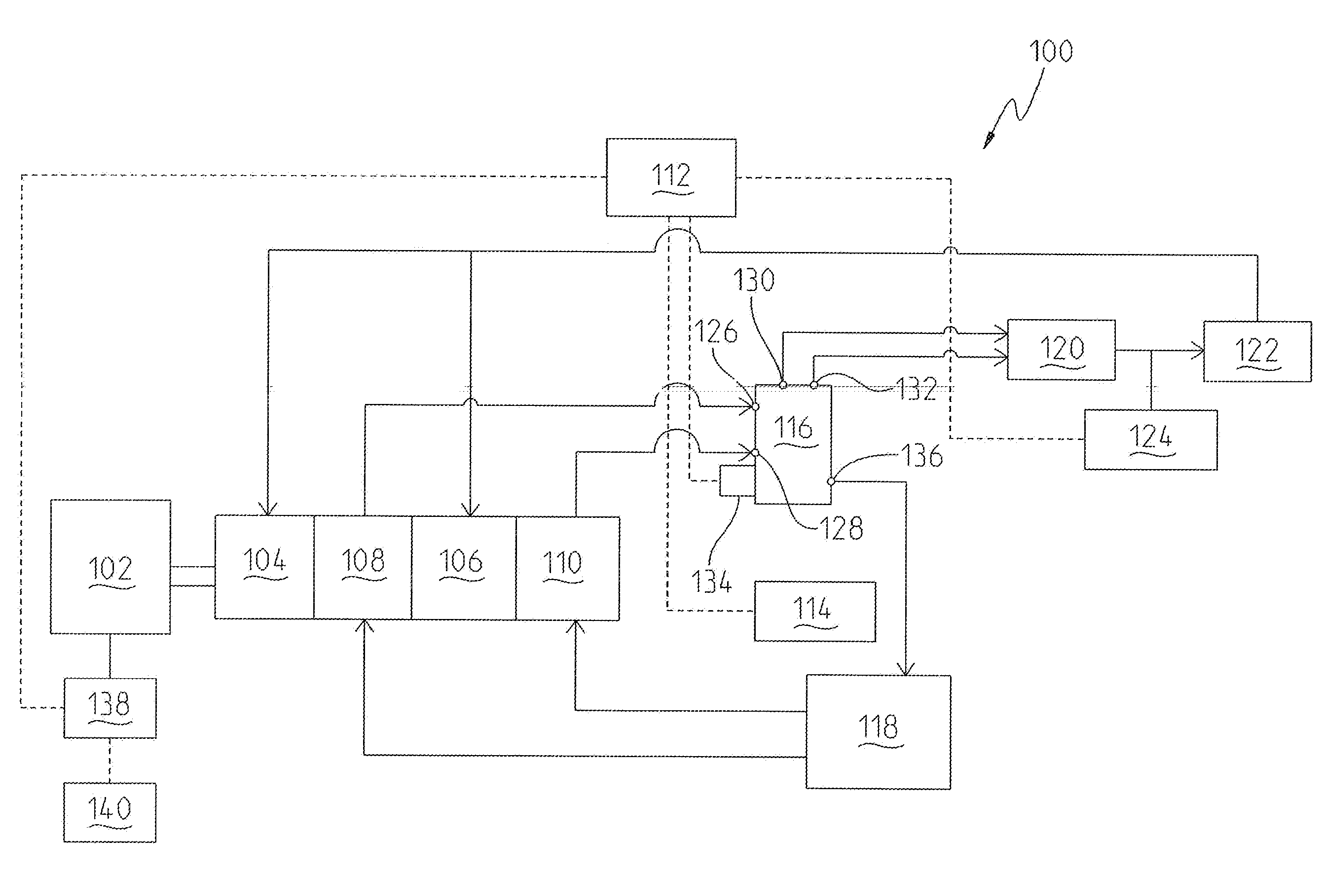
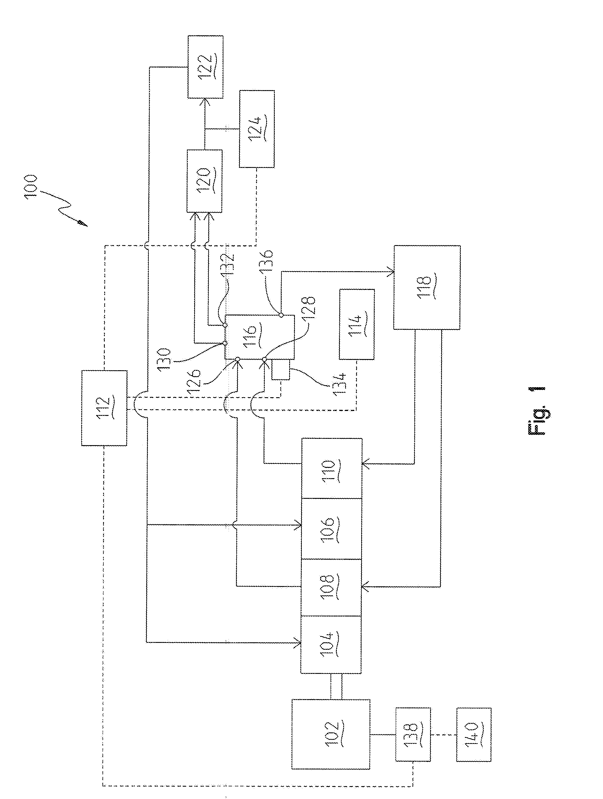
[0022]In the present disclosure, a means for diverting fluid flow is incorporated into a system to reduce a parasitic load during an engine start in cold temperatures. For purposes of this disclosure, a cold temperature refers to the temperature of oil in an engine or transmission system of a vehicle. The oil temperature is first measured, and based on the measurement, the system can either perform under normal conditions or activate a bypass system to reduce the parasitic load. An example of this is illustrated in FIG. 1.

[0023]An exemplary embodiment of an engine start system 100 of a vehicle is shown in FIG. 1. The engine start...


PUM


Abstract

The present invention provides an engine start system in a vehicle. The engine start system includes an engine and a charge system. The vehicle also includes an engine speed sensor for measuring a speed of the engine. The charge system is coupled to the engine and includes a charge pump. The vehicle further includes a control unit and a temperature sensor for sensing a temperature of fluid in the charge system. The temperature sensor is electrically coupled to the control unit. A bypass system is fluidly coupled to the charge system and includes a valve and a solenoid. The solenoid is electrically coupled to the control unit such that the control unit energizes the solenoid to control the valve in response to the speed measured by the speed sensor and the temperature sensed by the temperature sensor.

Description

FIELD OF THE INVENTION[0001]The present invention relates to a mechanism for initiating the start of an engine, and in particular to a bypass system for improving a cold engine start.BACKGROUND OF THE INVENTION[0002]In cold temperatures, conventional engines can have difficulty starting. There are several reasons for this depending on the type of engine. For example, for an engine that operates off a battery, batteries often have trouble during cold temperatures. Batteries include chemicals inside thereof that produce electrons, and chemical reactions inside the battery can take place slower in cold temperatures and thus produce less electrons. As a result, the starter motor has less energy when trying to start the cold engine, and therefore the engine cranks much slower when it is colder.[0003]Another reason for difficulty starting an engine during cold temperatures is the viscosity of the oil inside the starting system. Oil viscosity increases in cold temperatures and thus makes i...

Claims


Application Information

Patent Timeline
Patent Type & Authority Applications(United States)
IPC IPC(8): B60W10/04B60W10/10B60W30/18F15B21/045
CPCF02N19/001F15B2211/20523F15B21/045F15B2211/851F02N19/004F15B11/0423F15B2211/613F15B2211/62F02N2200/024F02N2200/023F15B2211/20576F15B2211/6309E02F9/2253F15B2211/6343F15B2211/526E02F9/2246Y10T477/688F02N2200/022F15B2211/50536F02N11/0848
Inventor KLOUSIA, HEIDI K.BENSON, CHRISTOPHER R.
Owner DEERE & CO
Why Eureka
Try Eureka