
Internal humidification in low temperature PEM fuel cell by means of a wick

a proton exchange membrane and fuel cell technology, applied in the field of new fuel cells, can solve the problems of adding to the parasitic power loss, adding to the system complexity, and humidifying gas, and achieve the effect of reducing the net parasitic load

Inactive Publication Date: 2017-05-18
COUNCIL OF SCI & IND RES
View PDF2 Cites 2 Cited by
  • Summary
  • Abstract
  • Description
  • Claims
  • Application Information

AI Technical Summary

Benefits of technology

The present invention provides a method of maintaining water content in a fuel cell membrane during operation using a cost-effective humidification technique. The method also reduces parasitic power loss by utilizing a passive means of water transport. Additionally, the invention increases the hydrophilic nature of the wicking material by treatment with acetone or Tin oxide.

Problems solved by technology

This forces the water to diffuse across the membrane from the water side to the gas side that subsequently evaporates at the membrane / gas interface resulting in humidification of gas.
The external humidification system adds to the parasitic power loss apart from adding to the system complexity.
However, the compressed air that is supplied to the cathode is too dry for maintaining proper moisture levels.
Former is energy intensive while use of latter normally results in less fuel utilization due to fuel crossover through the plates.
However, the drawbacks of such a configuration of fuel cell is that it is difficult to fabricate bipolar plates with wicking materials as channels and also usage of electrically insulating wicking material shall render increased resistance to charge transfer across the cells in a fuel cell stack.
The method though effective, does not alleviate the problem of easy manufacturing globally and works only with metallic plates.
The bipolar plate design provides an easy transport of water into the cell but is still quite complicated as it requires significant maneuvering in the bipolar plate design which incurs increment in manufacturing cost.
The wicking evaporative cooling described in the aforementioned publication is stated to require external water, from a source outside the fuel cell power plant, since the water generated at the cathode (process water) is said to be insufficient, except at startup, to achieve the necessary cooling.

Method used


Image

  • Internal humidification in low temperature PEM fuel cell by means of a wick
  • Internal humidification in low temperature PEM fuel cell by means of a wick
  • Internal humidification in low temperature PEM fuel cell by means of a wick

Examples


example 1

Measurement of Material Parameters Useful for Wicking Action and Thermal Stability:

[0058]Pore size distribution, gas permeability and contact angle play an important role for wicking action to take place in a porous hydrophilic material. It also gives an idea about the possibility of flooding of electrodes due to excess wicking. In order for wick to supply water to the fuel streams internally, it is essential that a positive wicking velocity be continuously maintained. Hence, optimum pore size distribution and permeability are critical for flood-free cell performance. Wicking action is in turn determined by using two important factors namely differential capillary pressure and wicking velocity. Differential capillary pressure (dPcap) is a function of surface tension of water, contact angle and pore diameter, whereas wicking velocity depends on the difference between dPcap and differential flow field pressure (dPflowfield), permeability, viscosity of fluid and channel length. Average...

example 2

Description of Experimental Configurations (A-D)

[0061]

TABLE 1Configu-Configu-Configu-Configu-ration Aration Bration Cration DPlacement ofNo wickOver anodeOver cathodeOver anodewickand cathodeExternalNoYesYesYeswater supplyto wickFlow mode atCounterCounter / CounterCounter / anodeCo-flowCo-flowFlow mode atCounterCounterCounter / Counter / cathodeCo-flowCo-flowMeans ofBubbleThroughBubbleThroughhumidificationhumidifierwickhumidifierwickat anodeMeans ofBubbleBubbleThroughThroughhumidificationhumidifierhumidifierwickwickat cathodeFeed at anodeHumidifiedDryHumidifiedDryFeed at cathodeHumidifiedHumidifiedDryDryInlet fuel50-5228-3050-5228-30temperature(° C.)Inlet oxidant45-4745-4728-3028-30temperature(° C.)

example 3

Control Experiment for Fuel Cell Performance (Configuration-A)

[0062]Configuration-A corresponding to the control single cell setup with external humidification of gases was taken as the base line performance for comparison with other configurations which make use of wick for internal humidification. The cell was supplied with 80% RH at the anode and 50% RH at the cathode. The humidification levels were maintained by controlling the humidifier temperature and gas line temperature. The gas line temperature was maintained at 60° C. for both anode and cathode. The humidifier temperature was maintained at 50° C. for anode and 45° C. for cathode. Galvanostatic polarization curve was recorded after cell stabilization for 6-8 h. The stoichiometry used for all tests was 1.2 for anode and 3 for cathode.


PUM

PropertyMeasurementUnit
thicknessaaaaaaaaaa
pore sizeaaaaaaaaaa
contact angleaaaaaaaaaa

Abstract

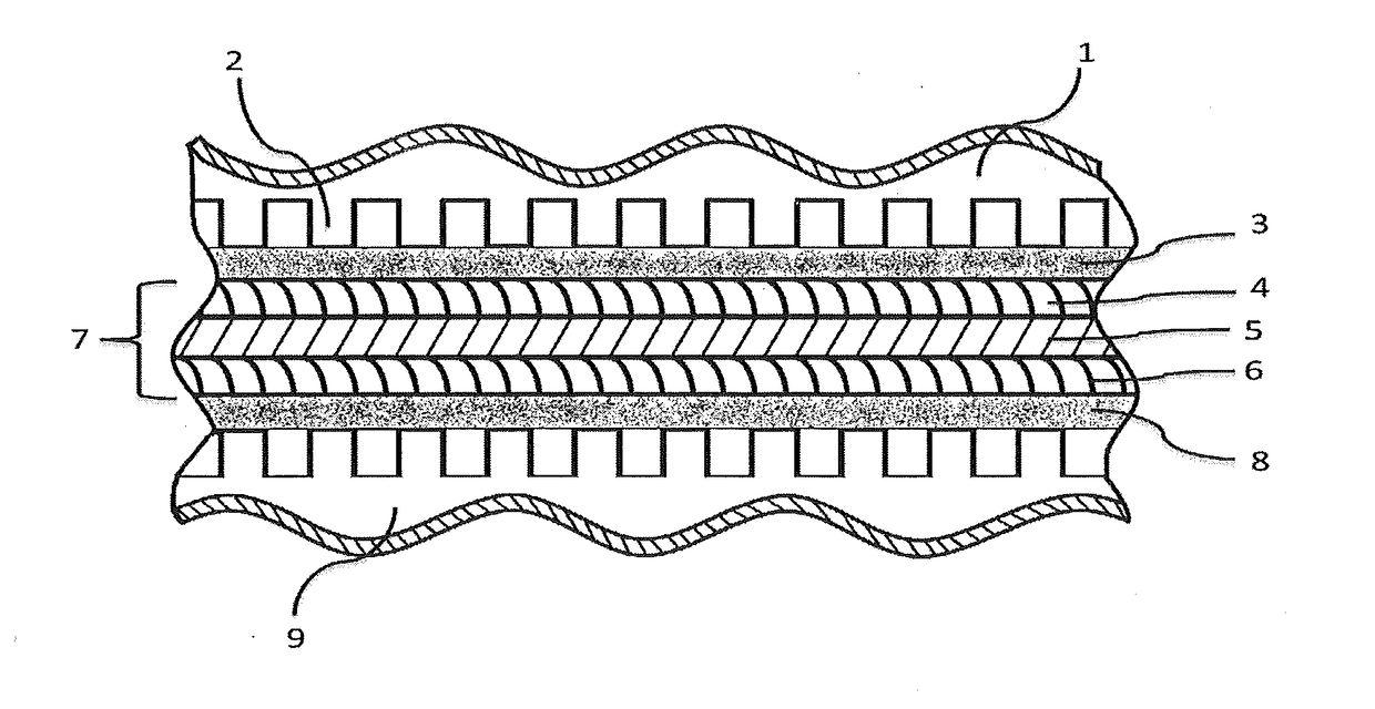
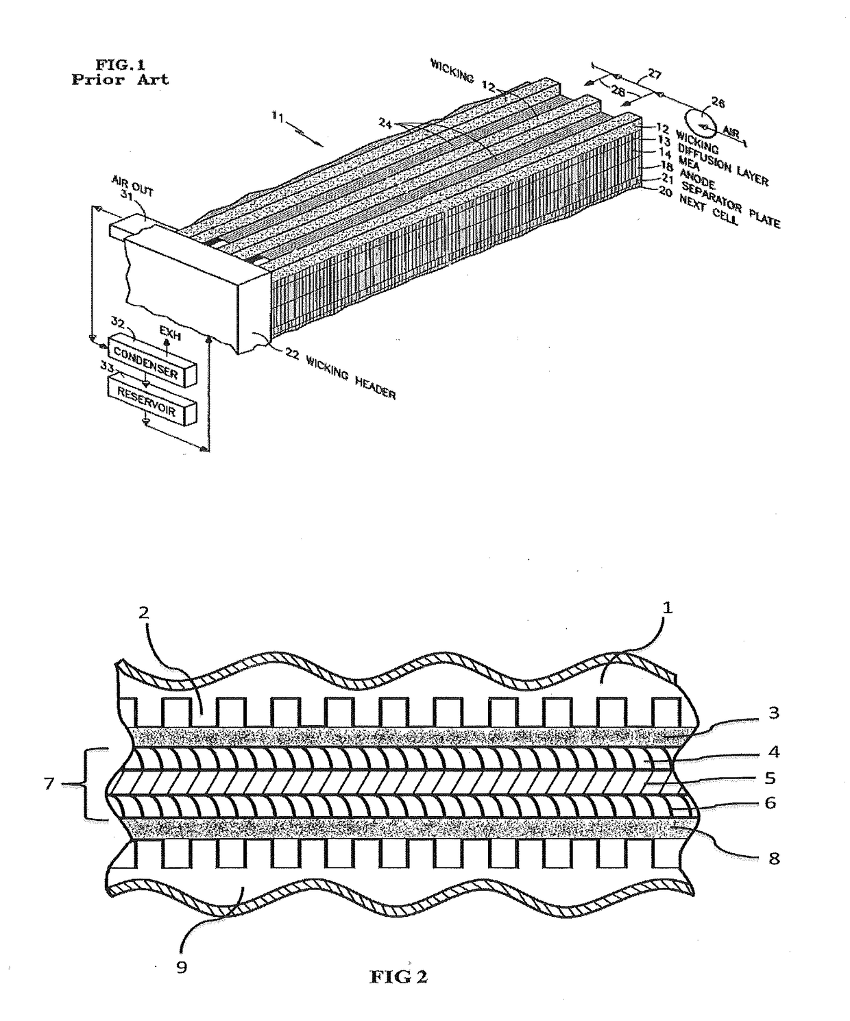
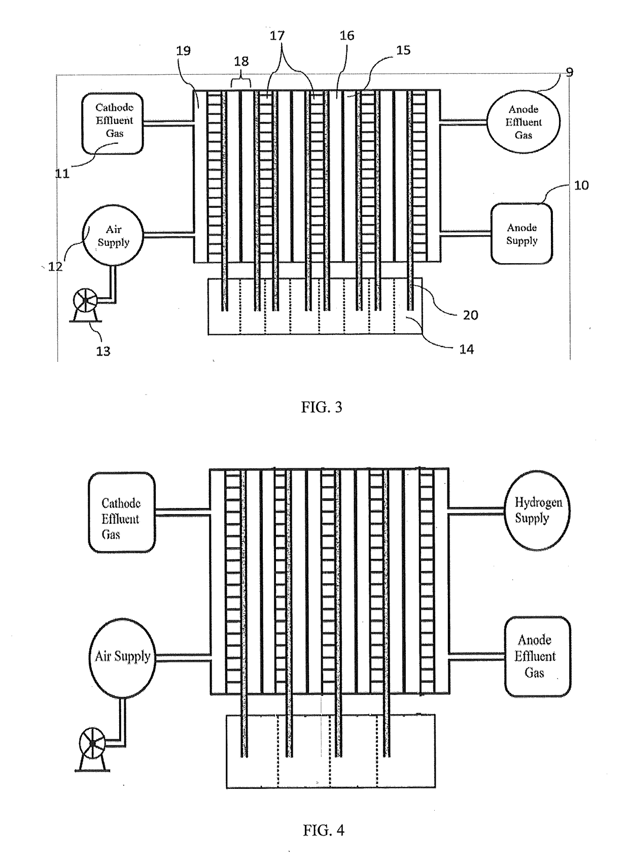
The present invention relates to a wick based technique for internal humidification in a low temperature proton exchange membrane fuel cell (LT-PEMFC) which comprises electrically conducting and hydrophilic wicking material (20) such as carbon cloth or metal foam placed over the entire active area of either one or both of the anode and cathode with the bottom portion of the wick (20) dipped in a trough (14) in order to facilitate capillary action for internal humidification, a trough (14) for water transport up the wicking material (20), dry feed and ambient (28-30° C.) temperature gas supply to either anode or cathode or both electrodes, counter and co-flow operation.

Description

FIELD OF INVENTION[0001]The present invention relates to a novel internal humidification technique for low temperature proton exchange membrane fuel cell (LT-PEMFC). More specifically, the invention relates to a wick based passive technique for supply of water directly to the membrane electrode assembly by capillary action which render simultaneous humidification and cooling of PEM fuel cells, with high electrical efficiency.BACKGROUND AND PRIOR ART OF THE INVENTION[0002]The proton exchange membrane used widely today by most PEMFC stack manufacturers is based on polyflouroethylenesulfonated polymer which requires sufficient levels of moisture content for effective proton transfer from anode to the cathode. Thus, it is needed that the gases supplied to the PEMFC are humidified either externally or internally to maintain the required moisture content in the membrane and to get continuous power output. In conventional systems, humidification of gas streams is achieved through external ...

Claims


Application Information

Patent Timeline
Patent Type & Authority Applications(United States)
IPC IPC(8): H01M8/04291H01M8/04119
CPCH01M8/04291H01M2008/1095H01M8/04149H01M8/04059H01M8/04126H01M8/04171H01M8/1007Y02E60/50
Inventor PANDEY, RAMENDRAAGARWAL, HARSHALKUMAR, RAMPARTHASARATHI, SRIDHARBHAT, SANTOSHKUMAR
Owner COUNCIL OF SCI & IND RES
Learn More