
Fuel cell water management

Inactive Publication Date: 2007-12-13
THE BOARD OF TRUSTEES OF THE LELAND STANFORD JUNIOR UNIV +1
View PDF7 Cites 10 Cited by
  • Summary
  • Abstract
  • Description
  • Claims
  • Application Information

AI Technical Summary

Benefits of technology

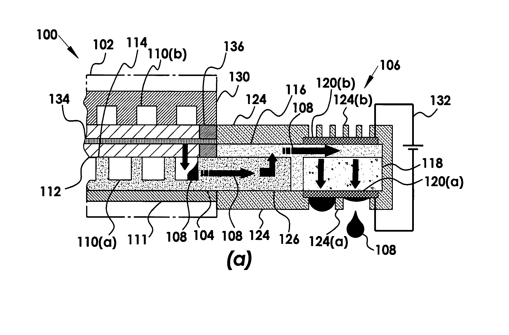
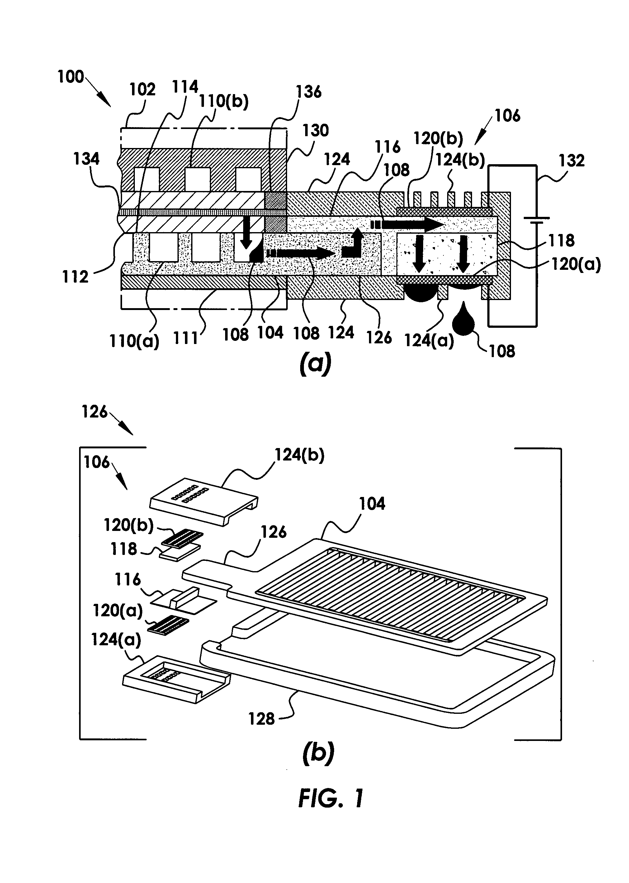
[0010] According to one aspect of the invention, the secondary porous structure layer is an electrical insulator between the pump and the fuel cell. The secondary porous structure layer is a particle filter to the pump, where the secondary porous structure layer can be polyvinyl alcohol sponge, glass microfiber, cotton paper, cotton cloth, wool felt, polyurethane foams, cellulose acetate, crosslinked polyvinyl pyrrolidone, or polyacrylamide. The porous pumping element can be glass-particle-packed fused silica capillaries, porous borosilicate glass, in situ polymerized porous monoliths, bulk-micromachined and anodically-etched porous silicon, aluminum oxide, porous silicon, or porous titanium oxide. In another aspect, the electroosmotic pump further includes an electric potential across the porous pumping element, where the electric potential is sufficient to induce a Columbic force on a mobile ion layer on the porous pumping element, whereas a viscous interaction between the mobile ions and the water generates a bulk flow. The electric potential across the porous pumping element can be a time varying potential, thus reducing parasitic loads to the fuel cell. The electric potential can be activated when flooding or dry-out is detected or imminent, whereby reducing parasitic loads to the fuel cell.
[0018] The proposed water management solution eliminates large fuel cell humidifier systems and reduces the size of air supply system by reducing the air flow requirements. This translates into reduction of power consumption, and complexity of auxiliary devices. Consequently, the proposed water management solution reduces the overall cost by reduction of system complexity and use of cost effective materials.

Problems solved by technology

Water management is a persistent challenge for PEM fuel cells with perfluorosulfonic acid (PFSA) type membranes, such as Nafion®, which require high water activity for suitable ionic conductivity.
Several problems exists when the liquid water invades the pores of the catalyst layer and the gas diffusion layer (GDL) and restricts diffusion of oxygen to the catalyst.
The primary problems occur when liquid water emerges from the GDL via capillary action.
The water accumulates in gas channels, covers the GDL surface, thus increasing the pressure differentials along flow field channels, and creating flow maldistribution and instability.
Currently, excessive air flow rates and serpentine channel designs are used to mitigate flooding at the cost of system efficiency.
Miniaturization of forced air fuel cells exacerbates this parasitic load issue as the efficiency of miniaturized pumps and blowers is typically much lower than that of macroscale pumps.
However, truly parallel channel architectures are typically impractical as they are prone to unacceptable non-uniformity in air streams and catastrophic flooding.
This design, however, did not offer improved power density due to a significant increase in the Ohmic losses introduced by the new components.
This approach had the undesirable effect of increased the parasitic loads and larger fuel cell size.
This attempt requires completely porous plates dedicated to internal water channels, where the system is complex requiring thick porous plates for relatively low volumetric power density.
There is an even greater need for such a device with miniaturized fuel cells, where the forced air exacerbates the parasitic load issue with the low-efficiency of miniaturized pumps and blowers.

Method used


Image

  • Fuel cell water management
  • Fuel cell water management
  • Fuel cell water management

Examples


Embodiment Construction

[0026] Although the following detailed description contains many specifics for the purposes of illustration, anyone of ordinary skill in the art will readily appreciate that many variations and alterations to the following exemplary details are within the scope of the invention. Accordingly, the following preferred embodiment of the invention is set forth without any loss of generality to, and without imposing limitations upon, the claimed invention.

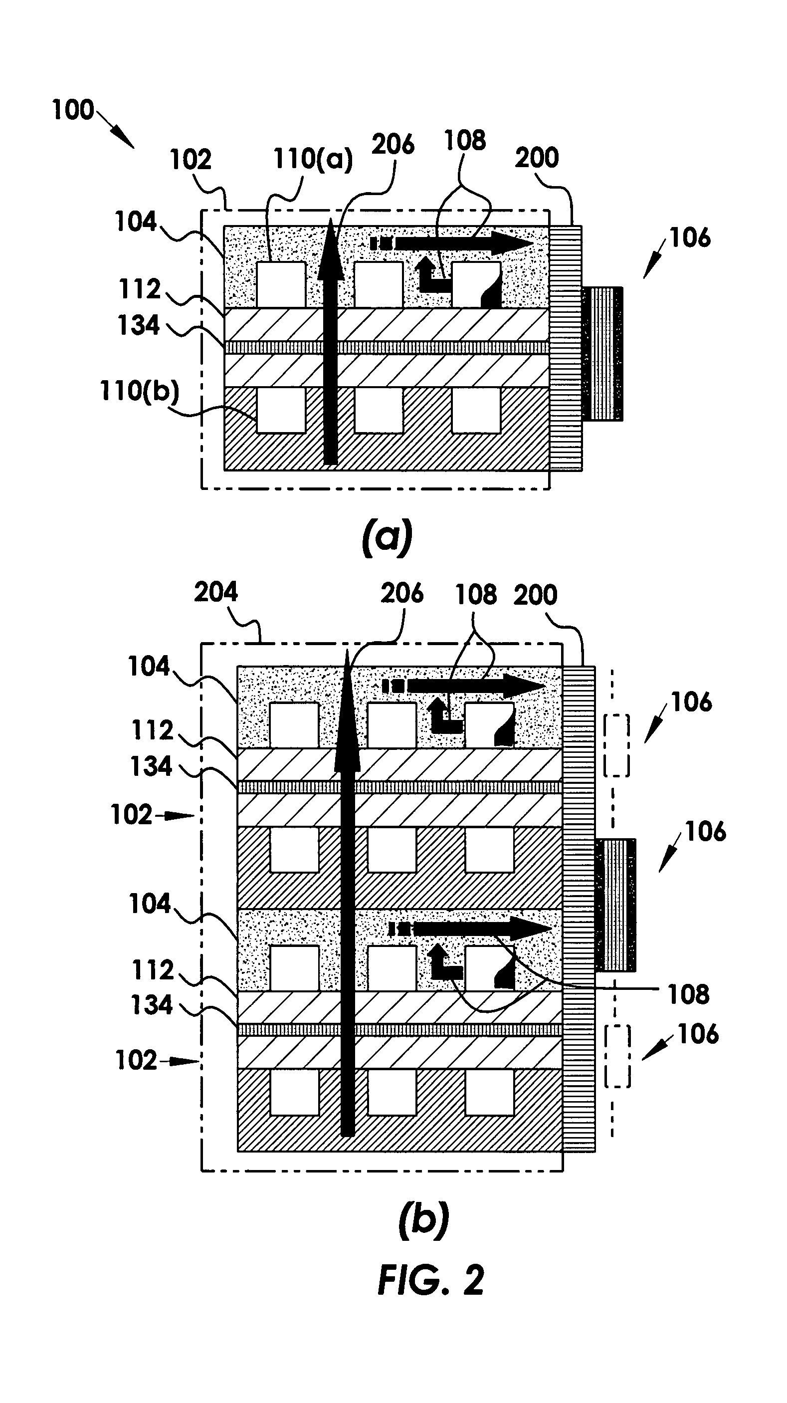
[0027] The current invention provides an active water management system utilizing electroosmtic (EO) pumps for redistributing and removing liquid water. Transient and polarization data demonstrate that the active removal of water with EO pumping according to the current invention eliminates flooding with a low parasitic load (˜10% of the fuel cell power). The EO pump uses an electric double layer (EDL) that forms between solid surfaces and liquids. By using porous glass EO pump structures, silanol groups on the surface of the glass spon...


PUM

PropertyMeasurementUnit
Electrical conductivityaaaaaaaaaa
Structureaaaaaaaaaa
Electric potential / voltageaaaaaaaaaa

Abstract

A polymer electrolyte membrane fuel cell water management device is provided. The device includes a hydrophilic water transport element spanning from inside the fuel cell to outside the fuel cell and disposed between a gas diffusion layer and a current collector layer in the cell. The transport element includes an intermediate wick outside the fuel cell that is hydraulically coupled to the transport element, and has a transport element structure integrated with a flow field structure within the fuel cell. The device further includes an electroosmotic pump, where the pump is located outside the fuel cell and is hydraulically coupled to the intermediate wick. The hydraulically coupled pump actively removes excess water from the flow field structure and the gas diffusion layer through the transport element, where a key aspect of the invention is the decoupling of water removal from oxidant delivery and reduced parasitic loads.

Description

FIELD OF THE INVENTION [0001] The invention relates generally to fuel cells. More particularly, the invention relates to fuel cells with wicking elements spanning from inside to outside the fuel cell with an outside wick portion hydraulically coupled to an elecroosmotic pump for water management. BACKGROUND [0002] Proton exchange membrane (PEM) fuel cells, also known as polymer electrolyte membrane fuel cells, require humidified gases to maintain proper membrane humidification. Water management is a persistent challenge for PEM fuel cells with perfluorosulfonic acid (PFSA) type membranes, such as Nafion®, which require high water activity for suitable ionic conductivity. Humidification of reactant gases ensures proper humidification of the membrane. Consequently, much of the water produced by the oxygen reduction reaction at the cathode is generated in liquid form. Several problems exists when the liquid water invades the pores of the catalyst layer and the gas diffusion layer (GDL)...

Claims


Application Information

Patent Timeline
IPC IPC(8): B01D61/42H01M8/04
CPCB01D63/082B01D2313/10B01D2313/12H01M8/0232Y02E60/50H01M8/0247H01M8/04149H01M8/04171Y02E60/522H01M8/0234H01M8/04B01D39/04B01D63/0822
Inventor FABIAN, TIBORLITSTER, SHAWNSANTIAGO, JUAN G.BULE, CULLENTSURU, HLDEAKLSASAHARA, JUNKUBOTA, TADAHLRO
Owner THE BOARD OF TRUSTEES OF THE LELAND STANFORD JUNIOR UNIV
Learn More