
Helical Clip and Method of Using the Same

a technology of helical clips and clips, which is applied in the field of retaining clips, can solve the problems of small diameter, difficult management of the trailing end portion, and large difficulty in adjusting the length of the guidewire, and achieves the effects of convenient use, simple and secure loading, and convenient us

Active Publication Date: 2012-08-30
SYNTERVENTION
View PDF11 Cites 5 Cited by
  • Summary
  • Abstract
  • Description
  • Claims
  • Application Information

AI Technical Summary

Benefits of technology

[0010]An advantage of the invention is to provide an apparatus to securely retain a medical wire to a medical surface while providing ease of loading and removal of the medical wire from the apparatus.

Problems solved by technology

This trailing end portion can be difficult to manage and requires special attention from the medical staff to ensure it does not become contaminated, tangled or confused with other wires in the procedural area.
Much of this difficulty comes from the length of the guidewires and catheters that can range from about 1 foot to about 10 feet or more.
Furthermore, these devices can be very small in diameter, making them very difficult to see and pick up, and are commonly made of stiff, springy materials that resist being looped or coiled into a shorter configuration.
When bent, there is always the possibility one end will become free and the device will spring uncontrollably and touch a non-sterile surface.
Once the device contacts a non-sterile surface, it is contaminated and must be replaced.
Placing the device back into the package can be difficult, time consuming and often damages the wire or catheter.
Manually coiling and wrapping the device around the coil can damage the catheter or wire, and may produce a configuration that must be untangled when it is needed again for the procedure.
Further, there is always the possibility of the coil unraveling and springing from the sterile area.
Using sterile gauze, tape, or towels to hold the coil has a high potential of lint or other contaminations being deposited into the device and has limited effectiveness.

Method used


Image

  • Helical Clip and Method of Using the Same
  • Helical Clip and Method of Using the Same
  • Helical Clip and Method of Using the Same

Examples


example 1

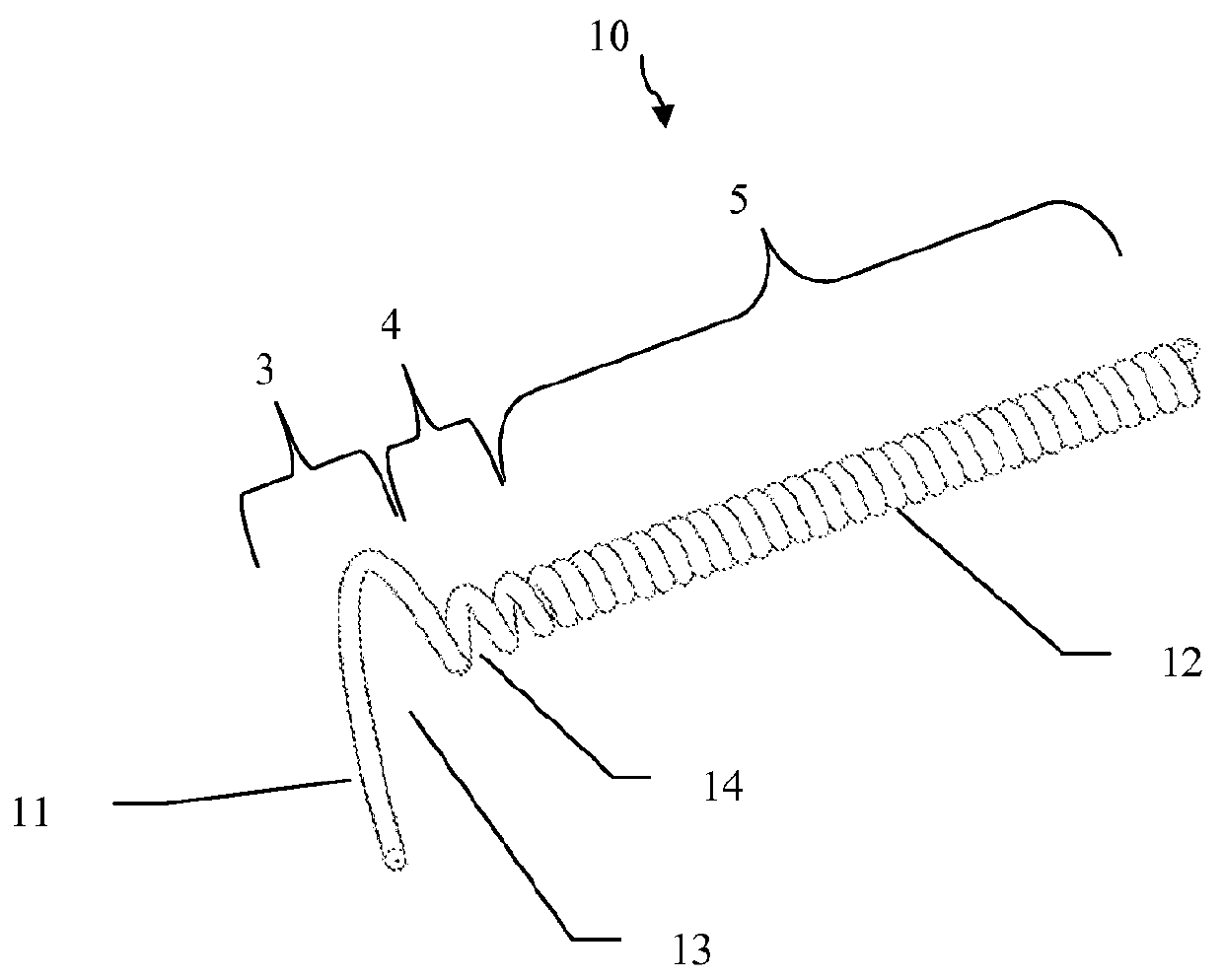
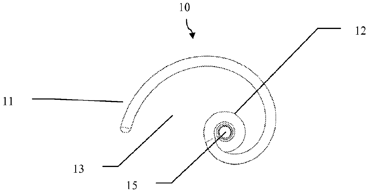
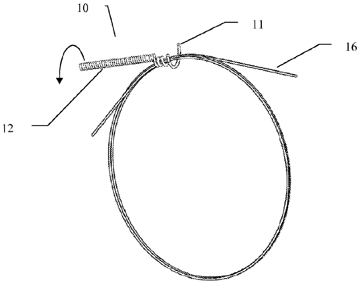
[0063]In this example, a retaining clip including a unitary helical structure was formed from a nylon monofilament wire having a diameter of about 0.033. The nylon monofilament wire includes a shaped leading edge, a loading channel, an inner lumen and a handle on a trailing end. The shaped leading edge was formed into a hooked shaped leading edge, inner lumen and channel configured to accept a portion of the medical device upon rotation of the handle.

[0064]The hooked shaped leading edge (Section 3 of FIG. 1) is about 0.09 inches in length with an inside diameter that tapers from about 0.82 inches to about 0.085 inches. The pitch at the leading edge starts at about 0.2 inches and reduces to about 0.05 inches at the other end. The next section (Section 4 of FIG. 1) is about 0.13 inches in length and has an inside diameter that tapers from 0.085 inches to 0.048 inches and the pitch tapers from 0.050 inches to 0.034 inches. The handle is about 2.3 inches in length and has a constant ins...


PUM


Abstract

The invention relates to a retaining clip for retaining at least one medical line in a shortened lateral position and / or to a supportive surface. In one embodiment, the device includes an elongated, tapered helical wire structure defining a hook shaped leading edge, a loading channel, an inner lumen and a handle on the trailing end. The hooked shaped leading edge, inner lumen and channel are configured to accept the largest diameter of medical wires the device is destined to be used with. Sections of the medical wire may be captured in the hook portion, and multiple rotations of the structure by the handle, moves the medical wire(s) into the channel and the inner lumen to be retained.

Description

[0001]This application claims the benefit of U.S. Provisional Patent Application No. 61 / 446,477, filed on Feb. 24, 2011, which is hereby incorporated by reference for all purposes as if fully set forth herein.BACKGROUND OF THE INVENTION[0002]1. Field of the Invention[0003]The invention relates to retaining clips and, more specifically, retaining clips for securing medical devices, such as, medical lines, catheters, guidewires, electrical lines, tubing, cables, and other elongated members.[0004]2. Discussion of the Related Art[0005]Guidewires and catheters are used in a variety of different medical procedures, for example during angiographic, endovascular, or surgical procedures. Guidewires are typically used to position catheters in a body lumen, for example arteries, veins or natural orifices within a mammal. The leading end portion of the guidewire is typically introduced into the body through an incision or natural orifice and then advanced to the treatment area. A catheter can b...

Claims


Application Information

Patent Timeline
IPC IPC(8): A61M25/09
CPCA61B19/0256A61M25/002A61B2019/267A61M2025/09125A61M2025/09116A61B90/57A61B50/20
Inventor TAYLOR, KEVIN D.
Owner SYNTERVENTION
Learn More