Optical communication module and optical fiber communication system

a technology of optical communication module and optical fiber communication system, which is applied in the direction of optical radiation measurement, instruments, spectrometry/spectrophotometry/monochromators, etc., can solve the problems of transmitter device upsizing or increasing costs, low precision, etc., and achieve high precision

Inactive Publication Date: 2012-09-06
HITACHI LTD
View PDF2 Cites 22 Cited by
  • Summary
  • Abstract
  • Description
  • Claims
  • Application Information

AI Technical Summary

Benefits of technology

[0021]According to the aspect of the present invention, the abnormal state of the optical fiber transmission line is detected with a high precision, and a supply state of the continuous wave light from the light source can be controlled,

Problems solved by technology

In this way, the related art system suffers from such a problem that the precision is low as a method of stopping the pump laser in the o

Method used


Image

  • Optical communication module and optical fiber communication system
  • Optical communication module and optical fiber communication system
  • Optical communication module and optical fiber communication system

Examples


first embodiment

1. First Embodiment

[0041]FIG. 4 illustrates an outline configuration of an optical communication module 400 according to a first embodiment. The optical communication module 400 includes an optical multiplexer 402, a coupler 403, a loss measurement unit 404, an optical fiber abnormality analyzer 405, a pump laser controller 406, and a pump laser 407.

[0042]Among those components, the loss measurement unit 404 monitors a loss of an ASE (Amplified Spontaneous Emission) that is generated in an optical fiber transmission line 401 by the pump light output from the pump laser 407, and propagated in a direction opposite to a traveling direction of the pump light. The loss measurement unit 404 monitors, for example, the attenuation of an optical intensity generated by bending of the optical fiber.

[0043]The optical fiber abnormality analyzer 405 detects whether there is an abnormal state of the optical fiber transmission line 401, on the basis of loss information of the ASE measured in the lo...

second embodiment

2. Second Embodiment

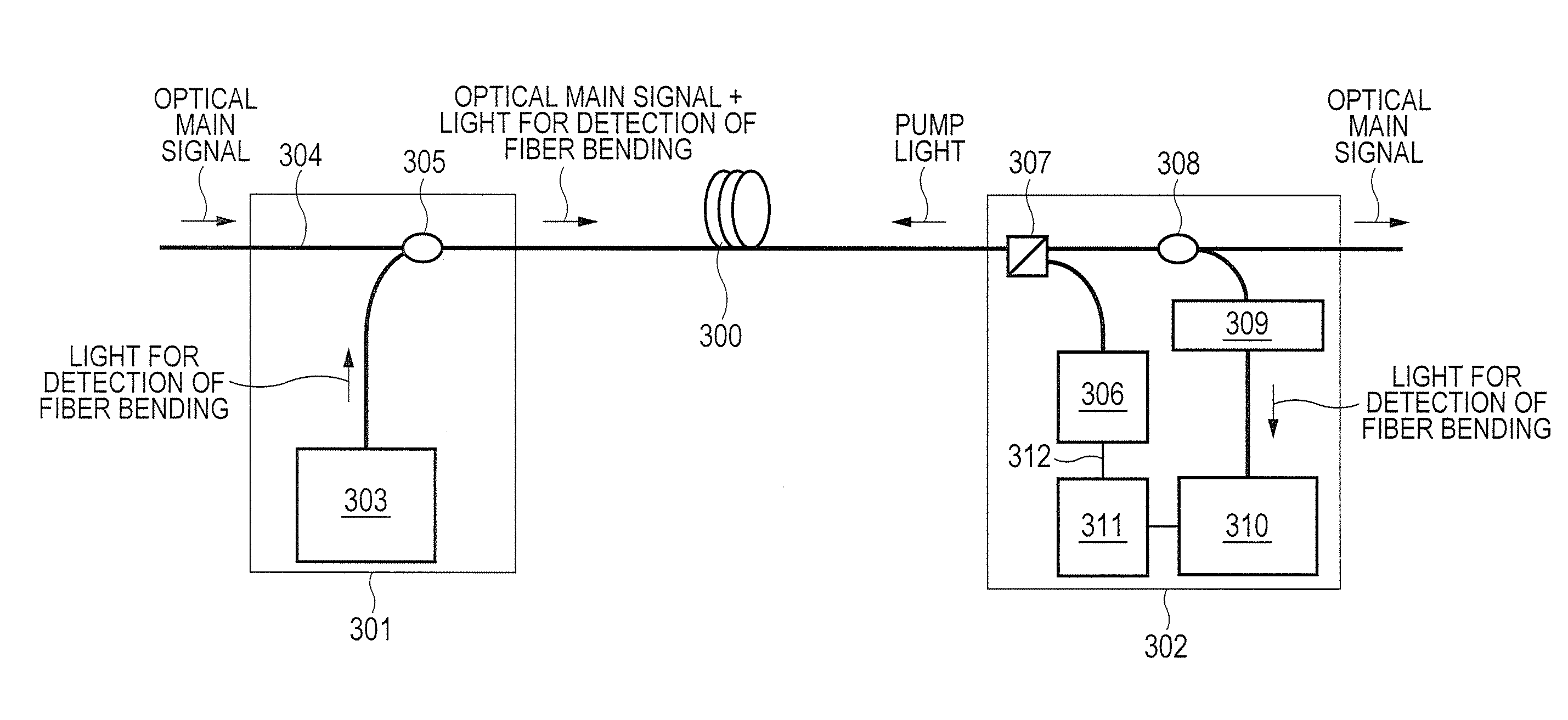
[0056]In a second embodiment, a description will be given of a system in which the occurrence of the fiber bending is detected on the basis of a loss difference between the optical noise in the long-wavelength side and the optical noise in the short-wavelength side which appear in the optical fiber which is a transmission line of the optical main signal.

[0057]FIG. 6 illustrates a block configuration of an optical Raman amplifier module 500 according to the second embodiment. In FIG. 6, the optical Raman amplifier module 500 is disposed downstream of an optical fiber transmission line 501 configuring the optical fiber communication system (backward pumping scheme). However, the optical Raman amplifier module 500 may be disposed at the upstream side with respect to the optical fiber transmission line 501, and may input the pump light toward the downstream side (forward pumping scheme). Also, the optical Raman amplifier module 500 may be disposed at both of the upst...

third embodiment

3. Third Embodiment

[0077]In a third embodiment, a description will be given of a system of detecting the occurrence of the fiber bending on the basis of the loss information of the long wavelength side noise light appearing in the optical fiber that is a transmission line of the optical main signal, and control information on the pump laser.

[0078]FIG. 8 is a block diagram illustrating a configuration of an optical Raman amplifier module 700 according to the third embodiment. In FIG. 8, the optical Raman amplifier module 700 is disposed downstream of an optical fiber transmission line 701 in the optical fiber communication system (forward pumping scheme). However, the optical Raman amplifier module 700 may be disposed at the upstream side with respect to the optical fiber transmission line 701, and may input the pump light toward the downstream side (forward pumping scheme). Also, the optical Raman amplifier module 700 may be disposed at both of the upstream and downstream sides with...


PUM


Abstract

Bending of an optical fiber where a heat may be generated by a high output power can be detected without using a dedicated light source. An optical communication module that outputs a continuous wave light generated by at least one light source to an optical fiber transmission line, includes: (1) a loss measurement unit that measures a loss of an amplified spontaneous emission generated by allowing the continuous wave light output from the light source to create stimulated Raman scattering in the optical fiber transmission line; (2) a fiber abnormality analyzer that detects the abnormal state of the optical fiber transmission line on the basis of loss information on the ASE measured by the loss measurement unit; and (3) a light source controller that controls a supply state of the continuous wave light from the light source on the basis of the detection of the fiber abnormality analyzer.

Description

CLAIM OF PRIORITY[0001]The present application claims priority from Japanese patent application JP 2011-046909 filed on Mar. 3, 2011, the content of which is hereby incorporated by reference into this application.FIELD OF THE INVENTION[0002]The present invention relates to an optical fiber communication system and an optical communication module configuring the system. The present invention relates particularly to a detection technique of optical fiber fault, and more particularly to a detection technique of optical fiber bending.BACKGROUND OF THE INVENTION[0003]In recent years, with the inventions and marketing of optical amplifiers (EDFA: Erbium Doped Fiber Amplifier), a required OSNR (optical signal noise ratio) has been remarkably relaxed. With this situation, a super high speed optical transmission in which a transmission capacity of one wavelength exceeds 10 Gbit / s has been put into practical use, and globally introduced. Further, the costs are further reduced with the use of ...

Claims


Application Information

Patent Timeline
IPC IPC(8): G01J3/44
CPCH04B10/0791H04B10/071
Inventor HIRAI, RIUKIKUCHI, NOBUHIKOUDA, TETSUYASASAKI, SHINYA
Owner HITACHI LTD
Why Eureka
Try Eureka