Unfortunately, ocular diseases can compromise vision of the eye and may cause
blindness in at least some instances.
Although treatment can be effective in many instances, in at least some patients may continue to lose vision under physician directed care.
Unfortunately, at least some of the current clinical techniques for measuring
glaucoma may not detect elevated IOP, such that a patient can lose vision and may even become blind in at least some instances.
As such pressure spikes may not be detected, the patient may not receive treatment in time to mitigate vision loss.
Further, at least some patients may not be able to visit the eye clinic on a strict regular basis, for example elderly patients and children, such that an increase in IOP may not be detected in a timely manner so as to prevent vision loss in at least some instances.
Also, in at least some instances a patient may simply forget to take his or her
medicine, such that the patient fails to follow the prescribed treatment.
Although measurements with an external IOP sensor can be helpful, these devices that measure pressure of the eye with an external sensor are somewhat indirect and can be inaccurate in at least some instances, such that the measured IOP may differ from the actual pressure inside the eye.
Such assumptions can lead to errors in the indirectly measured IOP when the
anatomy of the patient deviates from the assumed
normal anatomy and characteristics in at least some instances.
As a result, in at least some instances a patient may not receive appropriate treatment.
Although implantable shunt devices have been proposed to treat IOP with drainage of the eye, many of these shunt devices are not well suited for patients with IOP that can be controlled without surgical intervention, for example medically controlled with drugs.
The
insertion of such shunt devices can be more invasive than would be ideal, and in at least some instances shunt devices can cause the eye of the patient to be more susceptible to ocular trauma.
For example, at least some shunt devices are designed to drain liquid from the eye and include a substantial chamber portion inserted into the
sclera of the eye to drain liquid, such that the
sclera of the eye may be weakened in at least some instances.
Also, at least some of the current shunt devices can include rigid components that distort tissue and may result in ocular damage when the eye is subjected to trauma in at least some instances.
Further, implanted shunt devices can migrate from an implanted location and can contribute to infection in at least some instances.
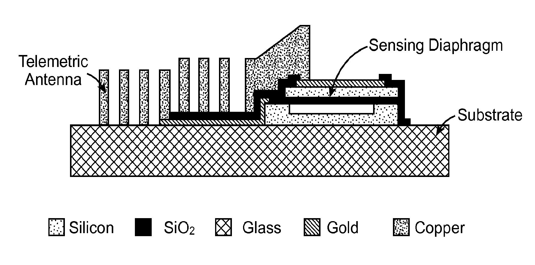
Therefore, integration of a
pressure sensor with a
shunt device can result in an
implant that is far more invasive and an eye that is more susceptible to injury than would be ideal in at least some instances.

