Cam driven wedge braking system for multi-stage lifts

a braking system and multi-stage technology, applied in the direction of lifting devices, lifting equipment safety devices, etc., can solve the problems of slowing down the inevitable collapse of the multi-stage lift system, damage to the multi-stage mast assembly, and not consistently working as intended, so as to improve the performance of the braking system, slow down the movement and collapse

Inactive Publication Date: 2012-09-13
ELEVATORSMART
View PDF5 Cites 21 Cited by
  • Summary
  • Abstract
  • Description
  • Claims
  • Application Information

AI Technical Summary

Benefits of technology

[0009]Embodiments herein provide a significantly improved multi-stage lift braking system, compared to the prior art previously mentioned, that will consistently function without inadvertent and unnecessary actuation and that will provide improved overall performance.
[0011]Embodiments here provide for a significant improvement in the performance of a braking system for a multi-stage lift assembly by providing a positive engagement method, through turning the knurled cam heads into a wedging position between multiple vertical members that move adjacent to each other, thereby stopping or substantially slowing down the movement and collapse of a multi-stage lift assembly. Embodiments herein avoid the gravity actuated nuisance tripping commonly occurring in existing braking systems today, because it actuates off cable tension versus gravity to engage and disengage the system.

Problems solved by technology

The device described in U.S. Pat. No. 4,015,686 did not consistently function as intended and was prone to failure because the locking pawl would not engage into the adjacent recess provided by the locking channel on the adjoining mast stage due to acceleration, or manufacturing alignment tolerances between the pawl and the channel, or if it did engage it would rip through the slotted channel only slowing down the inevitable collapse of the multi-stage lift system.
The device, when deployed in a real life cable break situation (and when it would actually function as intended), would frequently damage the multi-stage mast assembly, which is not ideal but was generally acceptable if life, limb, or property damage was averted.
In many cases a full engagement of the system would leave the multi-stage mast assembly so damaged that it would be completely unusable and unrepairable (scrap).
The device described in U.S. Pat. No. 5,645,142 functions fairly consistently but, since it is triggered by gravity versus lack of cable tension, it is prone to inadvertent nuisance tripping.
The inadvertent nuisance tripping of this device causes significant customer dissatisfaction and it is not uncommon that a multi-stage lift gets stuck in the elevated position and must be carefully laid down on it back by forklifts or other devices so that a service mechanic can use a special tool to disengage the wedge roller(s) from the wedge position(s).
This is an expensive situation as it involves a service call to a qualified mechanic and the act of taking a multi-stage lift that is in a vertical position 25 ft. in the air and laying it on its back in the horizontal position can be dangerous and may be very difficult to accomplish if the lift is in a tight location.

Method used


Image

  • Cam driven wedge braking system for multi-stage lifts
  • Cam driven wedge braking system for multi-stage lifts
  • Cam driven wedge braking system for multi-stage lifts

Examples


Embodiment Construction

[0027]In the following description, various embodiments of the present invention will be described. For purposes of explanation, specific configurations and details are set forth in order to provide a thorough understanding of the embodiments. However, it will also be apparent to one skilled in the art that the present invention may be practiced without the specific details. Furthermore, well-known features may be omitted or simplified in order not to obscure the embodiment being described.

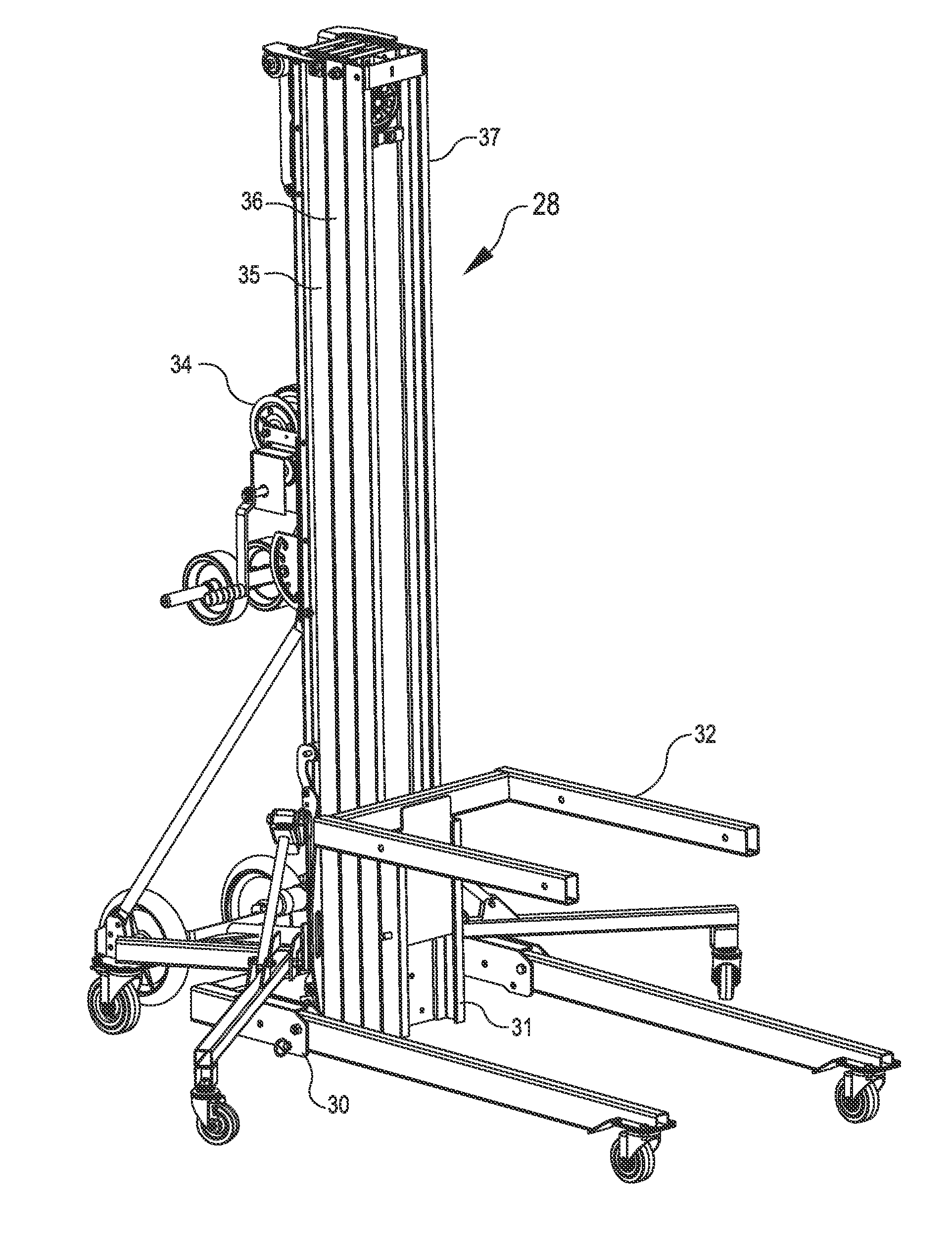
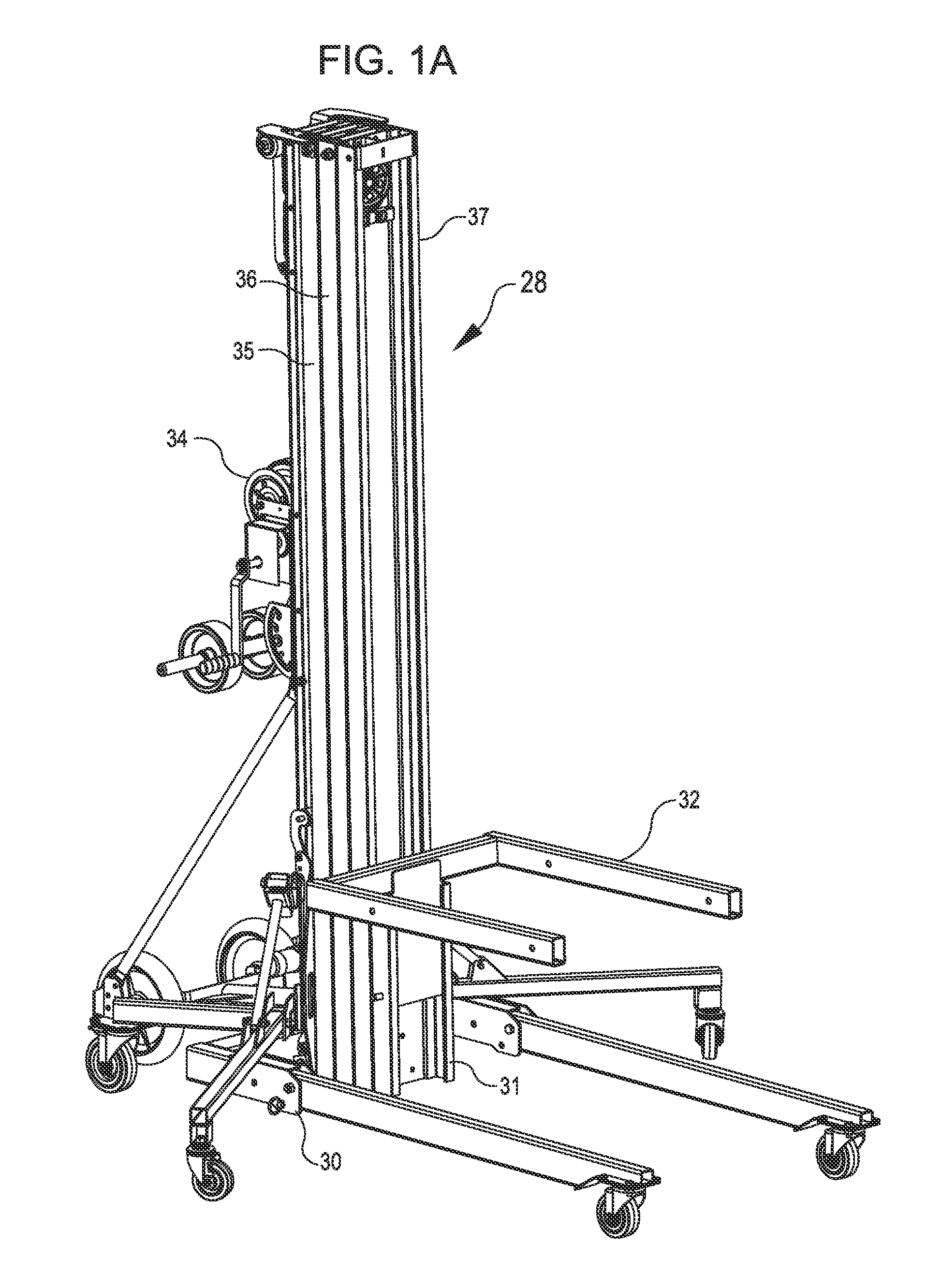
[0028]As shown in FIG. 1A, the braking system of in accordance with embodiments is shown operating in an improved portable multi-stage lift 28 to be now described having a mobile base assembly 30.

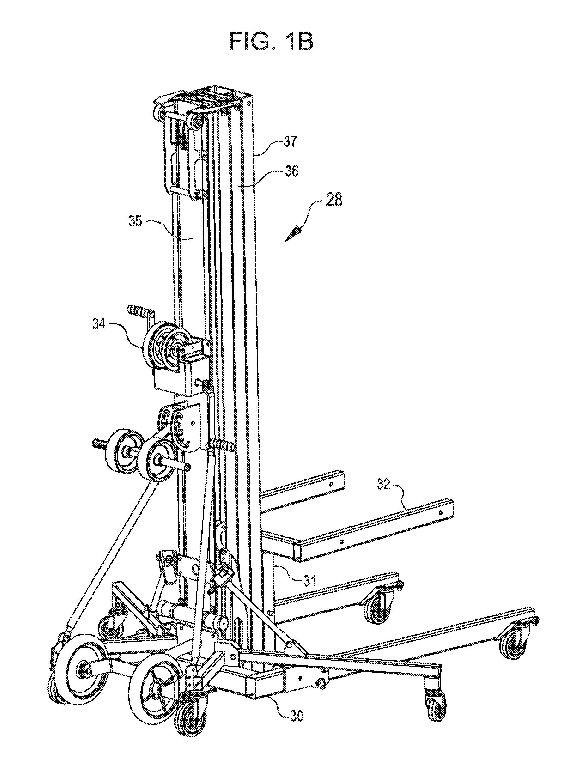
[0029]The lift 28 has a front carriage section 31 which can carry a load support 32. At the rear (FIG. 1B) the lift 28 has a winch 34 which may be manually operated or can be a motor driven unit. The winch 34 is mounted on the rear of a back stationary mast stage 35. For purposes of example, two extensibl...


PUM


Abstract

Apparatus for braking relative vertical movement between two vertical members includes linkage connected either directly or indirectly to a cable pulley-mount that is spring loaded and moves cams that wedge in between two vertically moveable members when cable tension is not present at the pulley. A broken cable, for example, will create a situation where there is no cable tension between a plurality of cable pulleys, the lack of cable tension moves the mechanical cam style linkage to engage the braking members.

Description

CROSS-REFERENCE TO RELATED APPLICATION[0001]The present application claims the benefit of provisional application No. 61 / 452,050 (Attorney Docket No. 92290-798359 (000200US)), filed on Mar. 11, 2011, the full disclosure of which is incorporated herein by reference.TECHNICAL FIELD[0002]The present invention relates to a braking system for stopping relative movement between the stages of a multi-stage lift in case of failure of the lifting mechanism such as, for example, failure of a cable when the lifting mechanism is a reeving system.BACKGROUND[0003]Several systems have been developed and patented over the years as part of an ongoing effort to continuously improve the safety of various lifting machinery. Embodiments herein contemplate a significant improvement over prior art both in the prevention of inadvertent nuisance tripping and the overall performance of the braking system of a multi-stage lift when actuated.[0004]U.S. Pat. No. 4,015,686 discloses a multi-stage lift which was ...

Claims


Application Information

Patent Timeline
Patent Type & Authority Applications(United States)
IPC IPC(8): B66F9/08B66F9/07
CPCB66F9/07559B66F17/003B66F9/087
Inventor BUSUTTIL, JOHN JOSEPHCITRON, STEVENMATTSON, MARK
Owner ELEVATORSMART
Why Eureka
Try Eureka