Systems and method for cooling a staged airblast fuel injector

Active Publication Date: 2012-09-13
ROLLS ROYCE PLC
View PDF4 Cites 35 Cited by
  • Summary
  • Abstract
  • Description
  • Claims
  • Application Information

AI Technical Summary

Benefits of technology

[0017]The present invention utilizes a pilot and a main fuel circuit layout which moves the main exit slots or ports to accommodate additional cooling channels

Problems solved by technology

One difficulty associated with operating a staged fuel injector is that when the pilot fuel circuit is operating alone during low power operation, stagnant fuel located within the main fuel circuit can be susceptible to carbon formation or coking due to th

Method used


Image

  • Systems and method for cooling a staged airblast fuel injector
  • Systems and method for cooling a staged airblast fuel injector
  • Systems and method for cooling a staged airblast fuel injector

Examples


Example

[0057]Referring now to FIGS. 8A through 11 which illustrate a second embodiment of the fuel injector of the present invention which has been designated as reference numeral 200. Fuel injector 200 is similar in construction and operation to injector 10, but as will be discussed below, the main and pilot fuel circuits have a difference layout and fuel channel geometry.

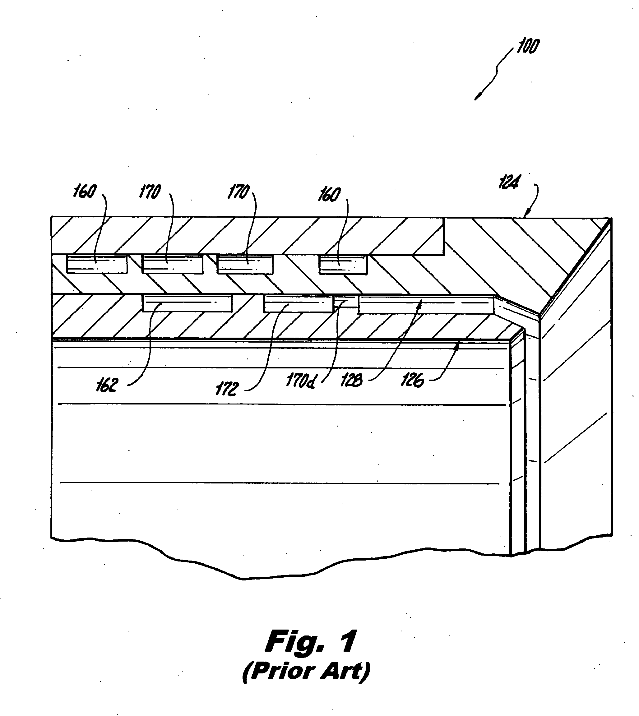
[0058]With specific reference to FIGS. 8A, 8B, 9A and 9B, the outer diametrical surface 224a of outer prefilmer 224 and the outer diametrical surface 226a of main fuel swirler 226 include machined channels or grooves that form portions of the main and pilot fuel circuits or pathways. More particularly, an outer pilot fuel circuit 260 and an outer main fuel circuit 270 are formed in the outer diametrical surface 224a of the outer prefilmer 224. The outer pilot fuel circuit 260 consists of two generally U-shaped fuel circuit half-sections 260a / 260b and a central section 260c. The outer main fuel circuit 270 includes a cent...

Example

[0066]Referring now to FIGS. 12 and 13 which illustrate a third embodiment of the fuel injector of the present invention which has been designated as reference numeral 300. Fuel injection 300 is similar to fuel injector 200, except that portions of fuel injector 300 have been formed as a unitary structure using direct metal laser sintering. More specifically, the prefilmer 324, the tube connector 312 and most of the main fuel swirler 326 have been integrally formed using additive manufacturing. In order to complete the assembly, the remaining portions, such as the forward portion of the fuel swirler can be formed by traditional machining and can be brazed to the unitary assembly formed using additive manufacturing.

[0067]Fuel injector 300 was formed using additive manufacturing, so as to have main 370 and pilot fuel circuits 360 / 362 arranged in a similar layout to those described with respect to fuel injector 200, except that the fuel circuits are formed internally rather than in the...


PUM


Abstract

The present invention is directed to a staged fuel injector that includes, inter alia, a main fuel circuit for delivering fuel to a main fuel atomizer and a pilot fuel circuit for delivering fuel to a pilot fuel atomizer which is located radially inward of the main fuel atomizer. The main fuel atomizer includes a radially outer prefilmer and a radially inner fuel swirler. Portions of the main fuel circuit are formed in the prefilmer and portions of the pilot fuel circuit are formed in the prefilmer and the fuel swirler and are positioned proximate to and in thermal contact with fuel exit ports associated with the main fuel circuit and formed in the prefilmer. As a result, the pilot fuel circuit cools the stagnant fuel located in main fuel circuit, including the exit ports, even when performing at engine power levels of up to 60% of the maximum take-off thrust.

Description

BACKGROUND OF THE INVENTION[0001]1. Field of the Invention[0002]The subject invention is directed to fuel injection, and more particularly, to systems and methods for cooling the exit ports of a main fuel circuit of a staged airblast fuel injector using the pilot fuel flow, at low engine power.[0003]2. Background of the Invention[0004]Staged fuel injectors for gas turbine engines are well known in the art. They typically include a pilot fuel atomizer for use during engine ignition and low power engine operation and at least one main fuel atomizer for use during high power engine operation in concert with the pilot fuel atomizer. One difficulty associated with operating a staged fuel injector is that when the pilot fuel circuit is operating alone during low power operation, stagnant fuel located within the main fuel circuit can be susceptible to carbon formation or coking due to the temperatures associated with the operating environment. This can degrade engine performance over time....

Claims


Application Information

Patent Timeline
IPC IPC(8): B05B17/04B05B1/14
CPCF23R3/28F23D2900/11101F23D11/107F23R3/343F02C7/2365
Inventor THOMSON, NEAL A.
Owner ROLLS ROYCE PLC
Why Eureka
Try Eureka