Wireless power transfer apparatus
- Summary
- Abstract
- Description
- Claims
- Application Information
AI Technical Summary
Benefits of technology
Problems solved by technology
Method used
Image

Examples
embodiment 1
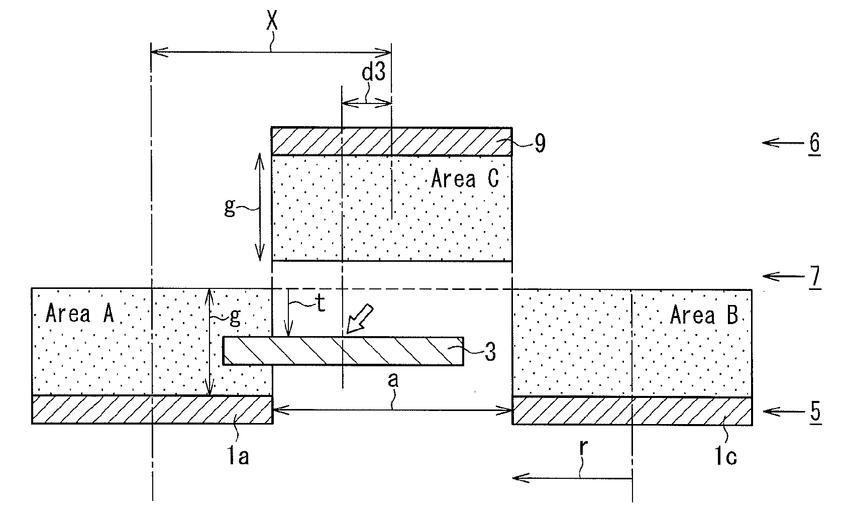
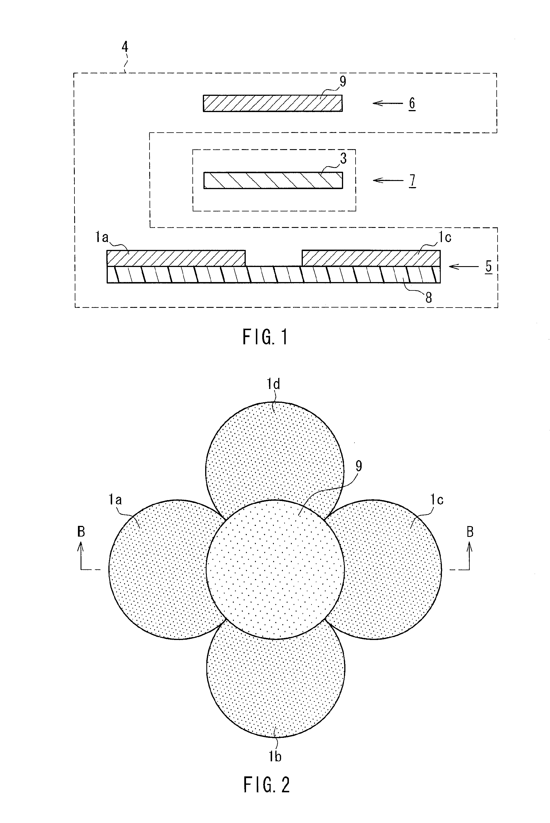
[0059]FIG. 1 is a cross-sectional view showing the configuration of a magnetic field resonance-type wireless power transfer apparatus according to Embodiment 1, and FIG. 2 is a plan view showing the configuration of the apparatus. FIG. 1 shows a cross section taken along the line B-B in FIG. 2. Note that the same components as those of the conventional wireless power transfer apparatus shown in FIGS. 26 to 28 are denoted by the same reference numerals and their description will not be repeated.
[0060]The wireless power transfer apparatus (power transmission apparatus) 4 according to this embodiment includes a first power transmission unit 5 disposed on the lower side and a second power transmission unit 6 disposed on the upper side of the apparatus. When the first power transmission unit 5 and the second power transmission unit 6 are arranged so as to oppose each other as in FIG. 1, a power receiving space of a predetermined size is formed between the power transmission units. A powe...
embodiment 2
[0080]FIG. 11A is a cross-sectional view showing the configuration of a magnetic field resonance-type wireless power transfer apparatus according to Embodiment 2, and FIG. 11B is a plan view showing the configuration of the apparatus. FIG. 11A shows a cross section taken along the line C-C in FIG. 11B.
[0081]This embodiment is directed to an exemplary arrangement of power transmission coils, which is intended to increase the possible power receiving area in the power transmission direction (the axial direction of each power transmission coil). In the exemplary arrangement shown in FIGS. 11A and 11B, the first power transmission unit 5 includes one power transmission coil 1, the second power transmission unit 6 includes one power transmission coil 9, and the central axes of the power transmission coil 1 and the power transmission coil 9 substantially coincide with each other. The first power transmission unit 5 and the second power transmission unit 6 are arranged so as to oppose each...
embodiment 3
[0085]A magnetic field resonance-type wireless power transfer apparatus according to Embodiment 3 will be described with reference to FIG. 12. In this embodiment, the power transmission coils are arranged in the same manner as the power transmission coils 1a to 1d and 9 in Embodiment 1 shown in FIG. 6. In FIG. 12, however, the power receiving coil 3 is disposed outside the possible power receiving area. In this case, although the displacement “d3” between the central axis of the power receiving coil 3 and the central axis of the power transmission coil 9 is within the radius “r”, the transfer efficiency decreases because the power receiving coil 3 is far away in the power transmission direction from the area C, in which the maximum power transfer efficiency can be obtained.
[0086]Thus, in this embodiment, the position of the power receiving coil 3 is monitored, and the power transmission coils 1a, 1c and 9 are moved to align the midpoint (distance “g”) between the plane position of t...
PUM
 Abstract
Description
Claims
Application Information
 - R&D
- Intellectual Property
- Life Sciences
- Materials
- Tech Scout
- Unparalleled Data Quality
- Higher Quality Content
- 60% Fewer Hallucinations
Browse by: Latest US Patents, China's latest patents, Technical Efficacy Thesaurus, Application Domain, Technology Topic, Popular Technical Reports.
© 2025 PatSnap. All rights reserved.Legal|Privacy policy|Modern Slavery Act Transparency Statement|Sitemap|About US| Contact US: help@patsnap.com