
Burners

a burner and burner technology, applied in the field of burners, can solve the problems of reducing the performance of the plant, high risk of flashback in at least one, and high cost of repair or replacement, so as to avoid flashback risk and facilitate operation

Inactive Publication Date: 2012-09-13
HAMWORTHY COMBUSTION ENG LTD
View PDF7 Cites 10 Cited by
  • Summary
  • Abstract
  • Description
  • Claims
  • Application Information

AI Technical Summary

Benefits of technology

[0013]It is a primary object of the present invention to enable a furnace to operate with a range of fuel gases wider than hitherto, including particularly gases with a higher concentration of hydrogen than hitherto. At the same time the invention facilitates operation without forced draught while meeting permitted noise levels and substantially avoiding a risk of flashback.

Problems solved by technology

Fuels with relatively high flame speeds, such as those containing relatively high proportions of hydrogen which are now increasingly used, may cause a flashback.
At a minimum, this reduces the performance of the plant; and if it results in damage to the burner, the cost of repair or replacement is considerable, especially if the plant has to be shut down.
With hundreds of burners in a typical furnace, the risk of flashback in at least one is high.
Hundreds of burners create a great deal of noise, from the combustion itself and from the delivery of combustion air, and the fact that the venturi tubes of the conventional burners provide hundreds of essentially straight passages through the wall of the furnace exacerbates the impact of this noise on the environment of the plant.
Generally, permitted noise levels are limited by environmental controls and / or health and safety regulations.
However, in conventional burners this constrains the flow of combustion air, so the risk of flashback is increased.
However this increases both capital cost and running cost, and also introduces another source of noise outside the furnace.

Method used


Image

  • Burners
  • Burners
  • Burners

Examples


Embodiment Construction

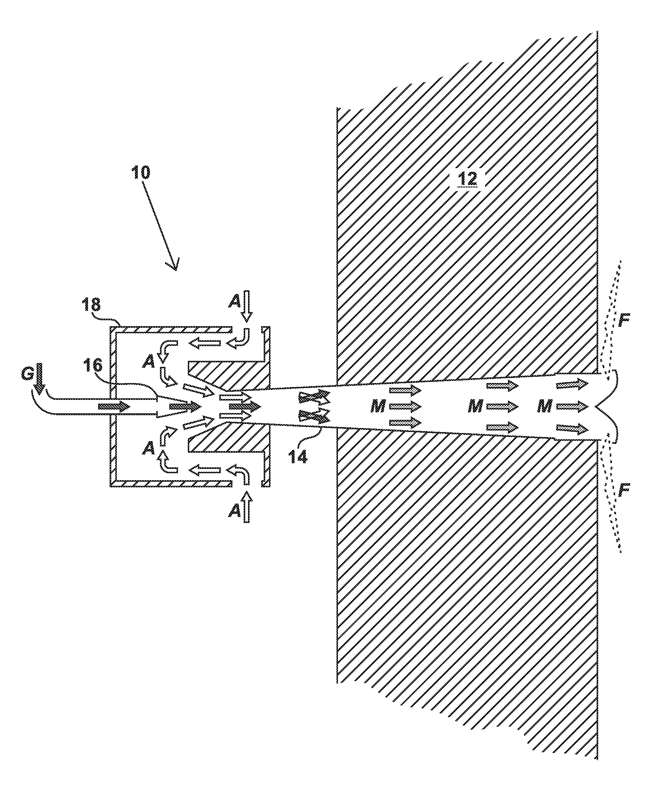
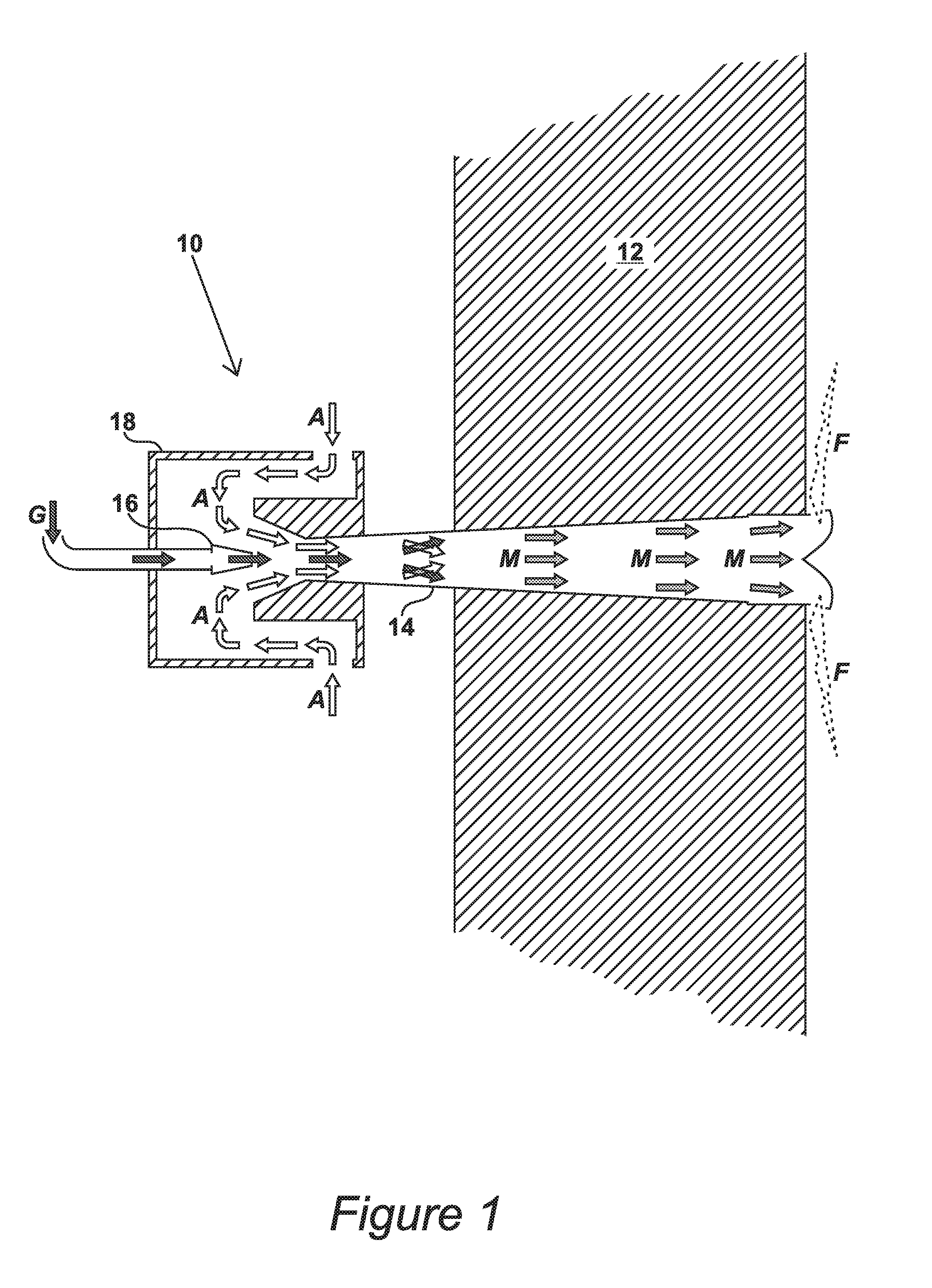
[0026]Referring first to FIG. 1, this shows a previously known burner indicated generally at 10 mounted in a wall 12 of a furnace for an endothermic process such as hydrogen reforming or ammonia reforming or ethylene cracking or EDC cracking. For simplicity and clarity of illustration, no attempt is made in the drawings to detail the construction of the furnace, including refractory brick or tile material carrying the burner 10 or practical operating features such as valves and igniters, all of which will be comprehended by those skilled in the science. It will also be understood that there will be hundreds of burners like the burner 10 in a typical furnace for endothermic processes.

[0027]The burner 10 is of the pre-mix type. It comprises a venturi tube 14 extending through the wall 12 from an outer, proximal, end to an inner, distal, end. At its proximal end gaseous fuel G (indicated in the drawings by dark arrows) is injected into the venturi tube 14 by way of a jet 16. Combustion...


PUM


Abstract

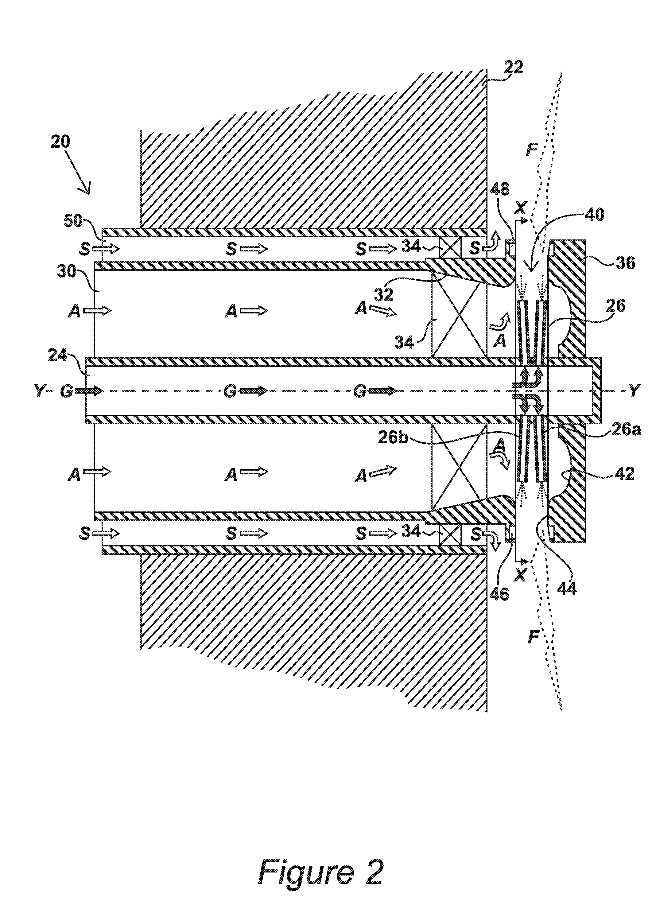
The invention provides a nozzle-mixed burner for use in an endothermic process such as hydrogen reforming or ammonia reforming or ethylene cracking or EDC cracking. The burner comprises a fuel duct extending axially through a wall of the furnace. The fuel duct delivers gaseous fuel to an array of nozzles extending laterally to spray the fuel outwardly into an annular chamber defined by a cap. Combustion air is delivered to the chamber by way of a primary air duct. A convergent-divergent section of the duct and an outwardly divergent section of the chamber together form a radially extending venturi. Combustion of the fuel, supplemented by the venturi effect, draws the air through the duct by natural inspiration.

Description

CROSS REFERENCE TO RELATED APPLICATIONS[0001]This application claims priority from United Kingdom Patent Application No. 10 14 969.8, filed Sep. 9, 2010 the entire disclosure of which is incorporated herein by reference in its entirety.BACKGROUND OF THE INVENTION[0002]1. Field of the Invention[0003]This invention relates to burners, particularly but not necessarily burners for use in radiant-wall side-fired furnaces of the kind used in endothermic processes such as hydrogen reforming, ammonia reforming, ethylene cracking and ethylene dichloride (EDC) cracking.[0004]2. Description of the Related Art[0005]Considering hydrogen reforming as an example, this is an industrial process for the production of hydrogen by reacting hydrocarbons such as natural gas with steam in the presence of a catalyst. In the primary reaction, methane reacts with water to yield carbon monoxide plus hydrogen:CH4+H2O→CO+3H2  [Equation 1][0006]The reaction is highly endothermic, and therefore the process is car...

Claims


Application Information

Patent Timeline
IPC IPC(8): F23D14/04F23C5/00
CPCF23D14/24F23D14/125F23D14/22
Inventor MOXHAM, CHRISTOPHER JOHNMOXHAM, BRADLEY CHARLESYOUNG, MARK
Owner HAMWORTHY COMBUSTION ENG LTD
Learn More