Ultrasound diagnostic apparatus

a diagnostic apparatus and ultrasonic technology, applied in the field of ultrasonic diagnostic apparatus, can solve the problems of further destabilizing the signal processing in the integrated circuit board, lowering the image quality of ultrasound images, and destabilizing the output signals of transmitted or received ultrasonic waves, so as to simplify the control of ultrasound transmission and reception, reduce the burden of ultrasound probes upon spatial compounding, and reduce the effect of reception

Active Publication Date: 2012-09-13
FUJIFILM CORP
View PDF5 Cites 50 Cited by
  • Summary
  • Abstract
  • Description
  • Claims
  • Application Information

AI Technical Summary

Benefits of technology

[0078]According to the ultrasound diagnostic apparatus in the second aspect of the invention, the frequency of the switching in the directions of ultrasound transmission and reception can be reduced also upon spatial compounding.
[0079]Therefore, the ultrasound diagnostic apparatus according to the second aspect of the invention is capable of ...

Problems solved by technology

As a result, output signals from the transmitted or received ultrasonic waves are destabilized to further destabilize the signal processing in the integrated circuit board.
That is, the heat generation from the probe lowers the image quality of ultras...

Method used


Image

  • Ultrasound diagnostic apparatus
  • Ultrasound diagnostic apparatus
  • Ultrasound diagnostic apparatus

Examples


first embodiment

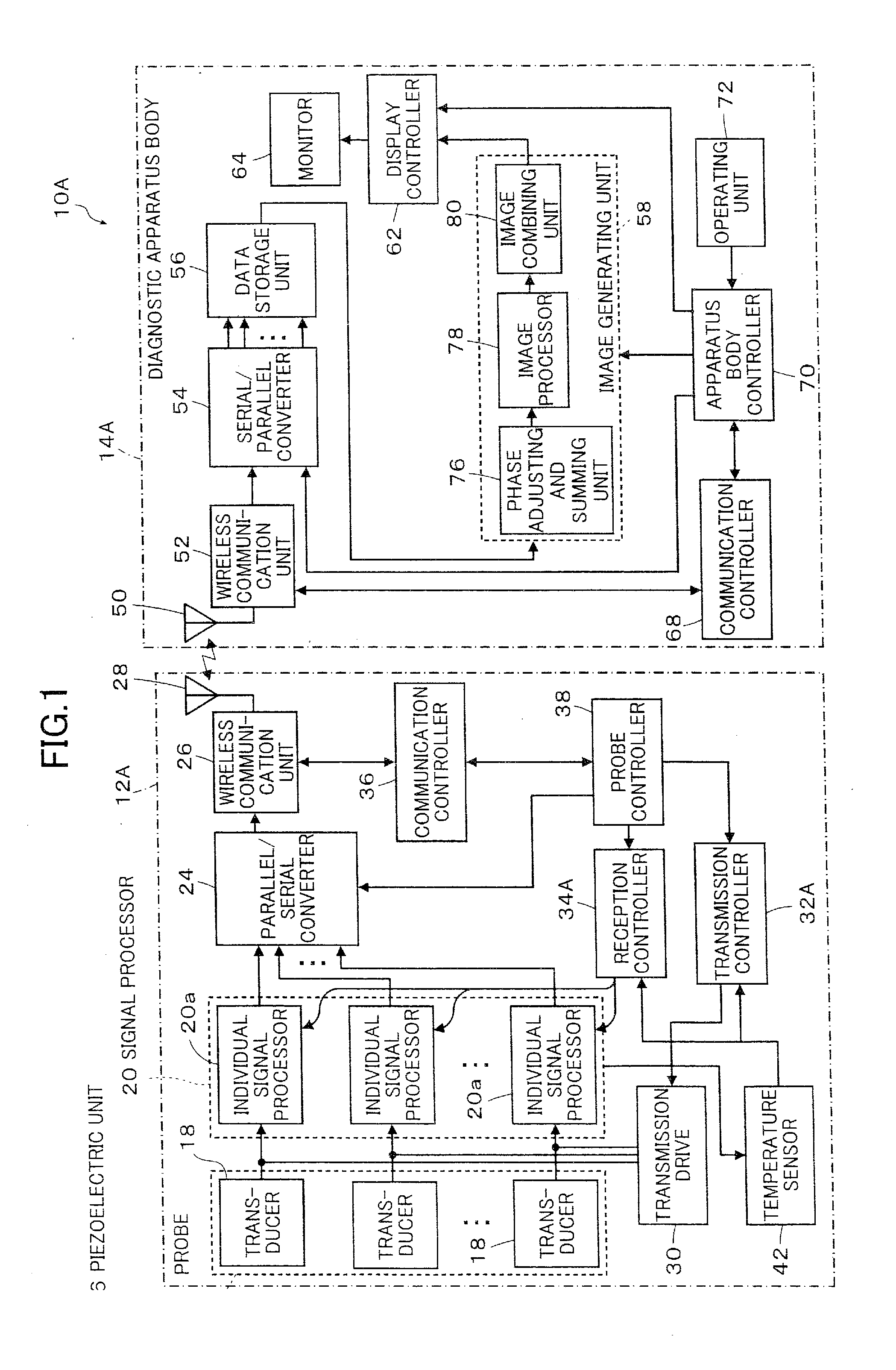
[0115]FIG. 1 is a conceptual block diagram showing the ultrasound diagnostic apparatus according to the first aspect of the invention.

[0116]An ultrasound diagnostic apparatus 10A shown in FIG. 1 includes an ultrasound probe 12A and a diagnostic apparatus body 14A. The ultrasound probe 12A is connected to the diagnostic apparatus body 14A by wireless communication.

[0117]The ultrasound probe 12A (hereinafter referred to as “probe 12A”) transmits ultrasonic waves to a subject, receives ultrasonic echoes generated by reflection of the ultrasound waves on the subject, and outputs reception signals of an ultrasound image in accordance with the received ultrasonic echoes.

[0118]In the practice of the invention, various known ultrasound probes can be used for the probe 12A. Therefore, there is no particular limitation on the type of the probe 12A and various types such as convex type, linear type and sector-type can used. The probe may be an external probe or a radial scan type probe for use...

second embodiment

[0230]FIG. 6 is a conceptual block diagram showing the second embodiment or the ultrasound diagnostic apparatus according to the first aspect of the invention.

[0231]Many components of the ultrasound diagnostic apparatus 10B shown in FIG. 6 are the same as those of the ultrasound diagnostic apparatus 10A shown in FIG. 1. Therefore, like components are denoted by the same reference numerals and the following description mainly focuses on the different features.

[0232]As in the first embodiment of the ultrasound diagnostic apparatus 10A, the ultrasound diagnostic apparatus 10B shown in FIG. 6 includes an ultrasound probe 12B (hereinafter referred to as “probe 12B”) and a diagnostic apparatus body 14B. As in the above embodiment, the ultrasound probe 12B is connected to the diagnostic apparatus body 14B by wireless communication.

[0233]Similarly to the probe 12A in the first embodiment, the probe 12B transmits ultrasonic waves to the subject, receives ultrasonic echoes generated by reflec...

third embodiment

[0335]FIG. 11 is a conceptual block diagram showing the ultrasound diagnostic apparatus according to the first aspect of the invention.

[0336]Many components of the ultrasound diagnostic apparatus 10C shown in FIG. 11 are the same as those of the ultrasound diagnostic apparatus 10A shown in FIG. 1. Therefore, like components are denoted by the same reference numerals and the following description mainly focuses on the different features.

[0337]As in the first embodiment of the ultrasound diagnostic apparatus 10A, the ultrasound diagnostic apparatus 10C shown in FIG. 11 includes an ultrasound probe 12C (hereinafter referred to as “probe 12C”) and a diagnostic apparatus body 14C. As in the above embodiment, the ultrasound probe 12C is connected to the diagnostic apparatus body 14C by wireless communication.

[0338]Similarly to the probe 12A in the first embodiment, the probe 12C transmits ultrasonic waves to the subject, receives ultrasonic echoes generated by reflection of the ultrasound...


PUM


Abstract

The ultrasound probe transmits and receives ultrasonic waves in different directions and the diagnostic apparatus body combines a plurality of images captured in the different directions of transmission and reception to produce an ultrasound image. In this process, the ultrasound diagnostic apparatus measures the temperature of the ultrasound probe to change the ultrasound transmission and reception for producing a composite ultrasound image or makes the directions of transmission and reception in the last ultrasound image in one composite ultrasound image coincide with those in the first ultrasound image in its temporally adjacent composite ultrasound image. The ultrasound diagnostic apparatus thus enables consistent ultrasound diagnosis against heat generated in the integrated circuit board of the ultrasound probe while simplifying the control of the ultrasound transmission and reception.

Description

BACKGROUND OF THE INVENTION[0001]The present invention relates to an ultrasound diagnostic apparatus. The invention more particularly relates to an ultrasound diagnostic apparatus capable of suppressing heat generation from an ultrasound probe while easily controlling the ultrasound transmission and reception in spatial compounding.[0002]Ultrasound diagnostic apparatus using ultrasound images are put to practical use in the medical field.[0003]In general, an ultrasound diagnostic apparatus includes an ultrasound probe (hereinafter referred to as “probe”) and a diagnostic apparatus body. In the ultrasound diagnostic apparatus, the probe transmits ultrasonic waves toward a subject and receives ultrasonic echoes from the subject. The diagnostic apparatus body electrically processes the reception signals received by and outputted from the probe to produce an ultrasound image.[0004]So-called “speckle” (speckle noise / speckle pattern) is known as a factor that may deteriorate the image qua...

Claims


Application Information

Patent Timeline
IPC IPC(8): A61B8/14
CPCA61B8/00A61B8/4472A61B8/5253A61B8/546G01S15/8995G01S7/5205A61B8/54G01S7/52079G01S7/52085A61B8/56A61B8/145A61B8/4444A61B8/5207G01S15/8915
Inventor TANABE, TSUYOSHI
Owner FUJIFILM CORP
Why Eureka
Try Eureka