Bone screw

Inactive Publication Date: 2012-09-13
SHANGHAI MICROPORT ORTHOPEDICS
View PDF20 Cites 10 Cited by
  • Summary
  • Abstract
  • Description
  • Claims
  • Application Information

AI Technical Summary

Benefits of technology

[0038]By means of the above structures, the capability of bearing the axial pullout force and the axial turning moment of the screw in the present embodiment is significantly improved.

Problems solved by technology

However, such a method may cause adverse effects on the other mechanical properties of the bone screw.
In particular, when the density of the threads is comparatively high, a sharp bending angle is likely to be formed at the root, whi

Method used


Image

  • Bone screw
  • Bone screw
  • Bone screw

Examples


Embodiment Construction

[0055]The detailed descriptions of the preferred embodiments of the present invention will be given in an exemplificative manner below by referring to the Drawings, so that those skilled in the art can understand the advantages of the present invention more clearly.

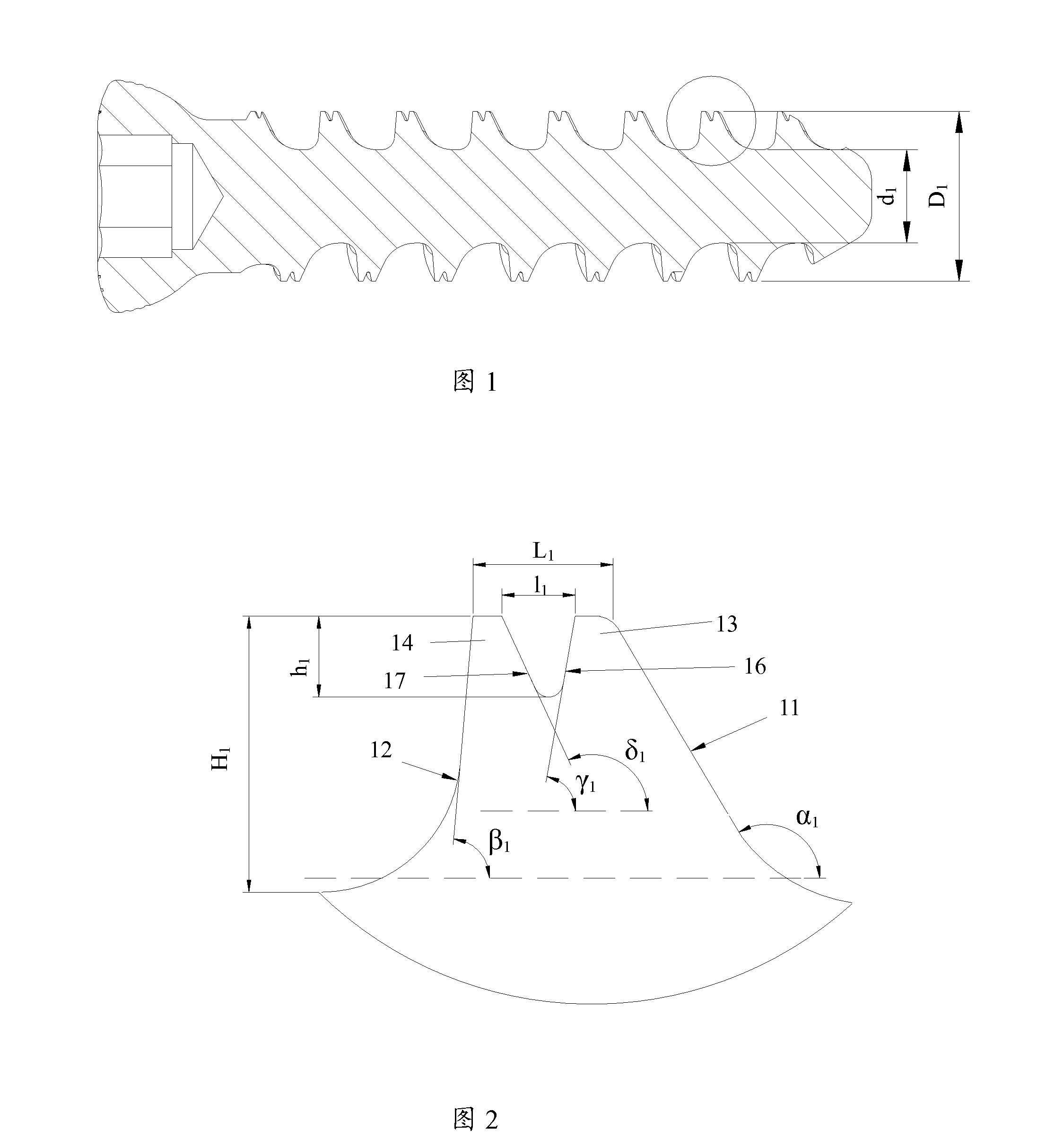
[0056]First referring to FIGS. 1 and 2, they show a preferred embodiment of a cervical screw designed according to the present invention and the tooth form structure thereof. The screw is used in an anterior cervical plate system, which has been widely applied in cervical spine operations and includes fixation plates and bone screws, wherein the fixation plates and bones are fixedly connected together by the bone screws, so as to achieve connection of broken bones or correction of trauma and abnormalities of bones using the rigidity of the plate.

[0057]It can be seen from FIG. 1 that the thread inner diameter of the first thread takes on a cylindrical shape, a diameter d1 is 2.2 mm, and an outer diameter D1 is 4.0 mm. Corr...


PUM


Abstract

A bone screw comprises a threaded portion. The threaded portion has a first thread including a first front surface (11), a first back surface (12) and a crest. A second thread including a second front surface (16) and a second back surface (17) is formed on at least part of the crest of the first thread. Because of the presence of the second thread, a contact area between the screw and a bone and an axial pullout force-bearing area are both significantly increased, without significantly influencing the bending resistance, so that the mechanical property of the screw is entirely improved.

Description

[0001]The present application claims a priority of the Chinese patent application No. 200910199188.6, entitled “Bone Screw”, which was submitted to the Chinese Patent Office on Nov. 20, 2009. All the contents of this Chinese patent application are incorporated into the present application by reference.TECHNICAL FIELD[0002]The present invention relates to a bone screw having improved mechanical characteristics, which is applicable to the connection of broken bones and the correction of trauma and abnormalities of bones at positions such as the cervical spine, the spine, the skull, etc.BACKGROUND ART[0003]In an orthopedic operation, a bone screw is generally used to connect broken bones or to correct various trauma and abnormalities of bones. Since bones are the main force receiving structures by which human bodies bear various mechanical loads, and broken bones that have been connected or the bones that have been corrected are likely to transfer the force loads borne to the bone scre...

Claims


Application Information

Patent Timeline
IPC IPC(8): A61B17/86
CPCA61B17/863A61B17/8625
Inventor WEN, XIAOYILI, JIELV, ZHENJIELIU, DAOZHI
Owner SHANGHAI MICROPORT ORTHOPEDICS
Why Eureka
Try Eureka