

Hydraulic brake system
a brake system and hydraulic technology, applied in the direction of brake control system, brake system, vehicle components, etc., to achieve the effect of avoiding the reduction of the operation feeling
- Summary
- Abstract
- Description
- Claims
- Application Information
AI Technical Summary
Benefits of technology
Problems solved by technology
Method used
Image

Examples
embodiment 1
[0187]There will be first described a vehicle on which a hydraulic brake system as the brake system according to the embodiment 1 is installed.
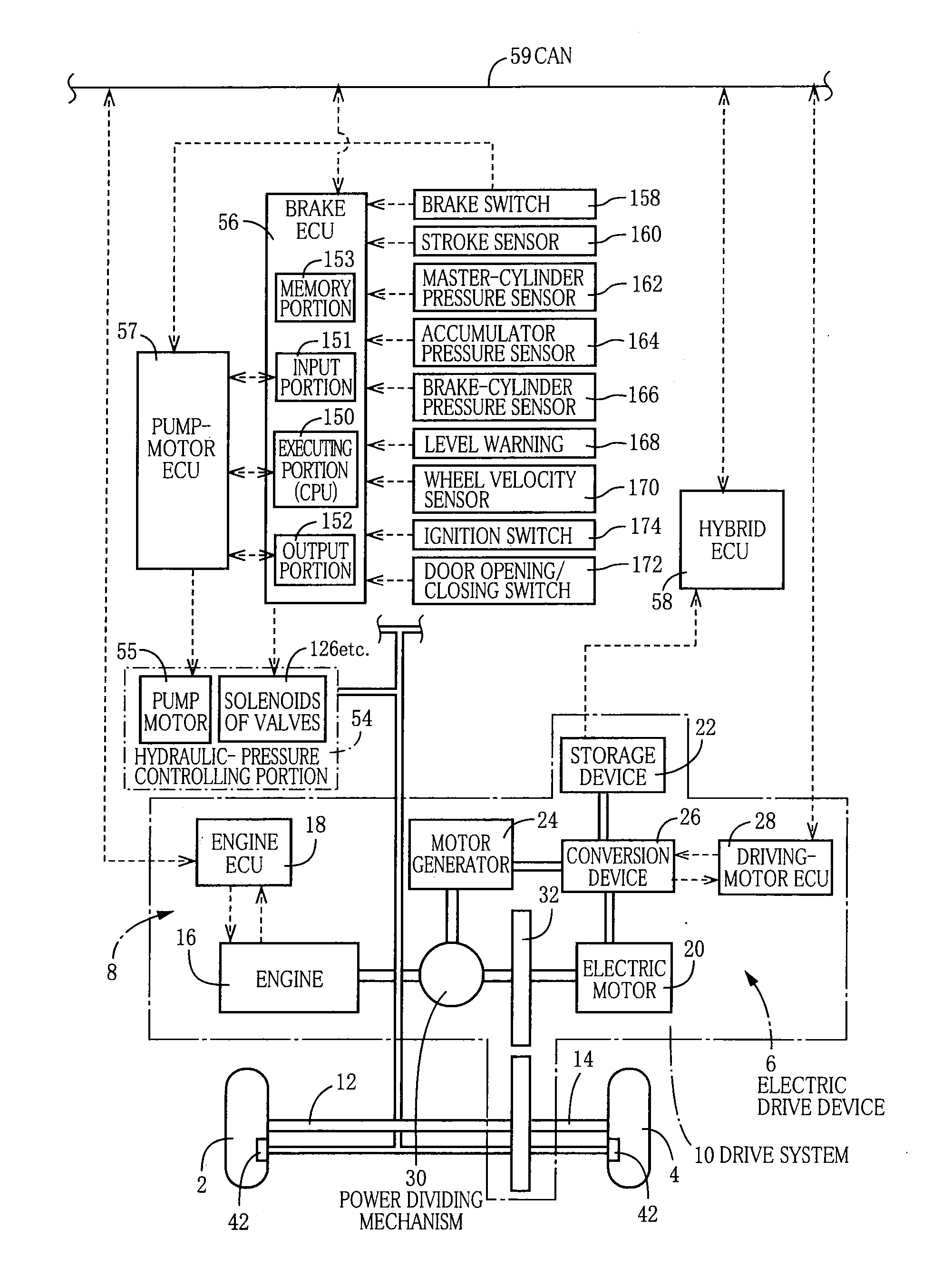
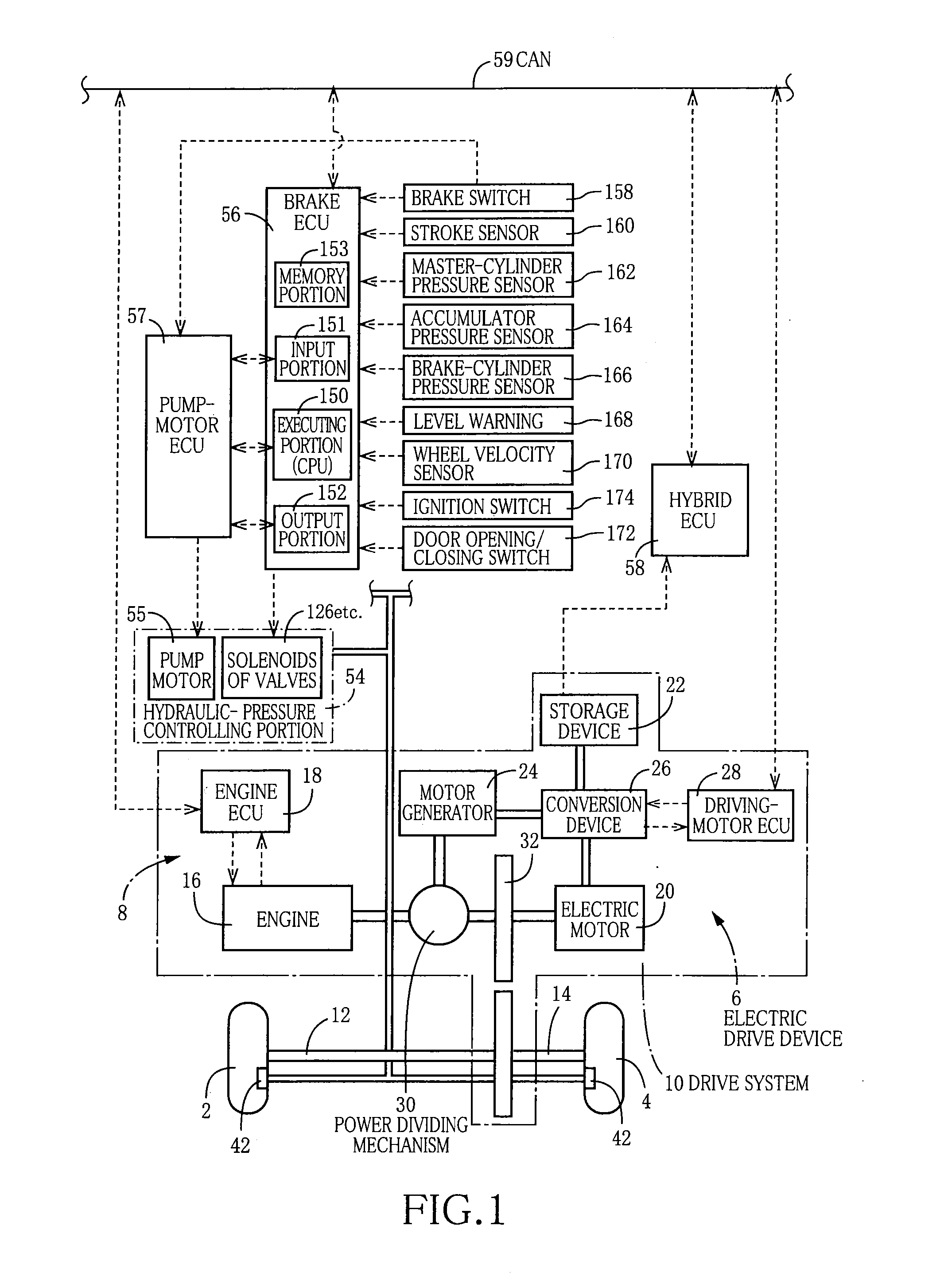
[0188]This vehicle is a hybrid vehicle including driving units in the form of an electric motor and an engine, so that front right and left wheels 2, 4 as drive wheels are to be driven by a drive system 10 including an electric drive device 6 and an internal-combustion drive device 8. A drive power of the drive system 10 can be transmitted to the front right and left wheels 2, 4 via drive shafts 12, 14. The internal-combustion drive device 8 includes an engine 16 and an engine ECU 18 that is configured to control activation of the engine 16. The electric drive device 6 includes a driving electric motor (hereinafter referred to as a driving motor) 20, a storage device 22, a motor generator 24, a conversion device 26, a driving-motor ECU 28 and a power dividing mechanism 30. The driving motor 20, motor generator 24, engine 16 and power dividing...
embodiment 2
[0328]In a hydraulic brake system according to Embodiment 2, an electric power source line of the hydraulic brake system is constituted by a double line. FIG. 13 shows an example of the brake system according to Embodiment 2.
[0329]In the present embodiment, for example, the brake ECU 56, the sensors 160-174 and the solenoids of all the electromagnetic valves are connected to the main electric power source 188 (that may be constituted by either a device identical with the storage device 22 or a device different from the storage device 22), while the pump-motor ECU57, the pump motor 55 and the brake switch 158 are connected to both of the main electric power source 188 and the sub-electric power source 189. Therefore, even in a case when electric energy cannot be supplied from the main electric power source 188, or a case when the electric system is in failure, the pump motor 55 can be activated as long as electric energy can be normally supplied from the sub-electric power source 189...
embodiment 3
[0330]FIG. 14 shows a brake circuit of a hydraulic brake system according to embodiment 3.
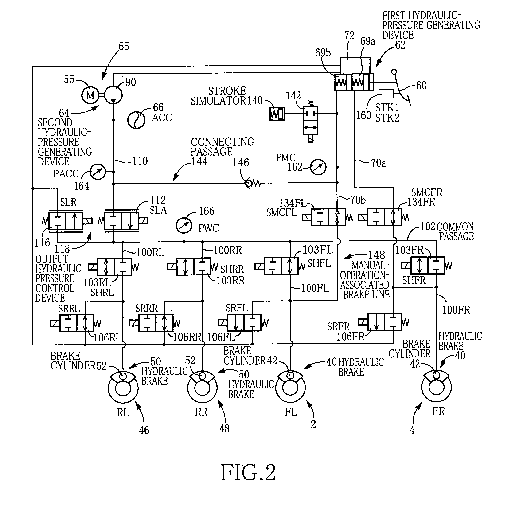
[0331]In the present embodiment, a connection passage 190 is provided to connect a connected portion of the controlled-pressure passage 110 and a connected portion of the second master cylinder passage 70b. The connected portion of the controlled-pressure passage 110 is located between the pressure-increasing linear control valve 112 and a portion of the controlled-pressure passage 110 to which the accumulator 66 is connected. The connected portion of the second master cylinder passage 70b is closer to the brake cylinder 42 than the second master cut-off valve 134FL. Further, like in Embodiment 1, a relief valve 192 as a flow restraining device is provided in a midway of the connection passage 190.
[0332]During activations of the hydraulic brakes 40, 50, the second master cut-off valve 134FL is in principle being placed in the closed state. Therefore, in Embodiment 1, in event of leakage occurri...
PUM
 Abstract
Description
Claims
Application Information