Fluorescent lamp drive and a protection circuit therein

a protection circuit and fluorescent lamp technology, applied in the direction of electric discharge lamps, discharge tubes/lamp details, discharge tubes incandescent screens, etc., can solve the problem of inefficient illumination of fluorescent lamps, and achieve the effect of high accuracy and efficient turning on

Inactive Publication Date: 2012-09-20
SANYO ELECTRIC WORKS LTD
View PDF3 Cites 22 Cited by
  • Summary
  • Abstract
  • Description
  • Claims
  • Application Information

AI Technical Summary

Benefits of technology

[0048]Therefore, if the LEDs that make up the light source of the lighting device encounter a short-circuit failure, the failure detection unit incorporated in the lighting device detects the failure, and based on a result of the detection, the failure alert unit can perform the failure alert operation to enable suggesting the need to repair or replace the lighting device comparatively early, so that it is possible to prevent an overcurrent due to the short-circuit failure from further expanding hazards of the failure.
[0049]As described hereinabove, the failure detection unit can detects whether each drive current flowing through the plurality of LED circ...

Problems solved by technology

It causes a problem that the fluore...

Method used


Image

  • Fluorescent lamp drive and a protection circuit therein
  • Fluorescent lamp drive and a protection circuit therein
  • Fluorescent lamp drive and a protection circuit therein

Examples


first embodiment

The First Embodiment

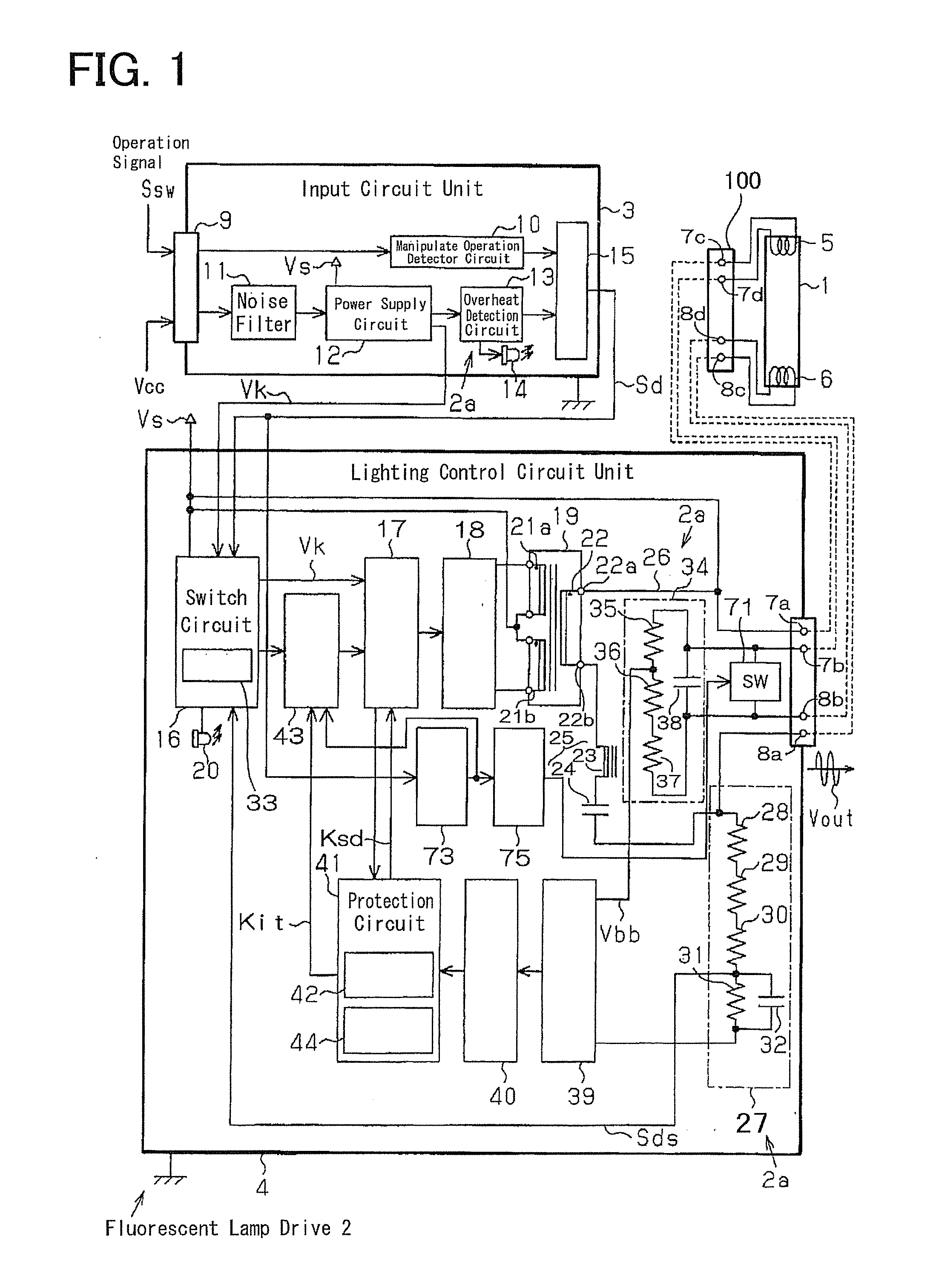
[0077]Hereafter, the first embodiment of the protection circuit of the fluorescent lamp drive which materialized the present invention is explained according to the FIG. 1 to FIG. 5.

[0078]First, a fluorescent lamp 1 which is controlled its power ON and OFF with the fluorescent lamp drive 2 concerning the first embodiment is described.

[0079]As shown in FIG. 1, the fluorescent lamp 1 is a cylindrical type fluorescent lamp, and a pair of filaments are formed on the connectors fixed to the opposite ends, respectively.

[0080]Concerning a filament 5, one of them, the first terminal (power supply side terminal) of the first filament 5 is configured to connect electrically to the first contact button 7a of the lighting control circuit unit 4 via the power supply side contact button 7c prepared in the fluorescent lamp attachment 100. And the second terminal (non-power supply side terminal) is configured to connect electrically to the first contact button 7b of the lighting...

second embodiment

The Second Embodiment

[0125]Next, the second embodiment of the present invention is explained according to FIG. 6. This embodiment differs to the first embodiment in controlling turning on and off of the fluorescent lamp 1 by software circuitry. So the same number is given to the equivalent elements as the first embodiment, and the details are omitted and only different elements are described fully.

[0126]As shown in FIG. 5, the operation controller 51 which controls programmably turning on and off of the fluorescent lamp 1 is provided in the fluorescent lamp drive 112. The operation controller 51 employs a software circuit comprising CPU (Central Processing Unit) 52 and memory 53, and performs lighting and turning off operation according to the control program 54 stored in the memory 53. Moreover, the operation controller 51 consists of a control IC (Integrated Circuit) formed into one chip. The operation controller 51 of this embodiment is a circuit which works equivalently to the e...

third embodiment

The Third Embodiment

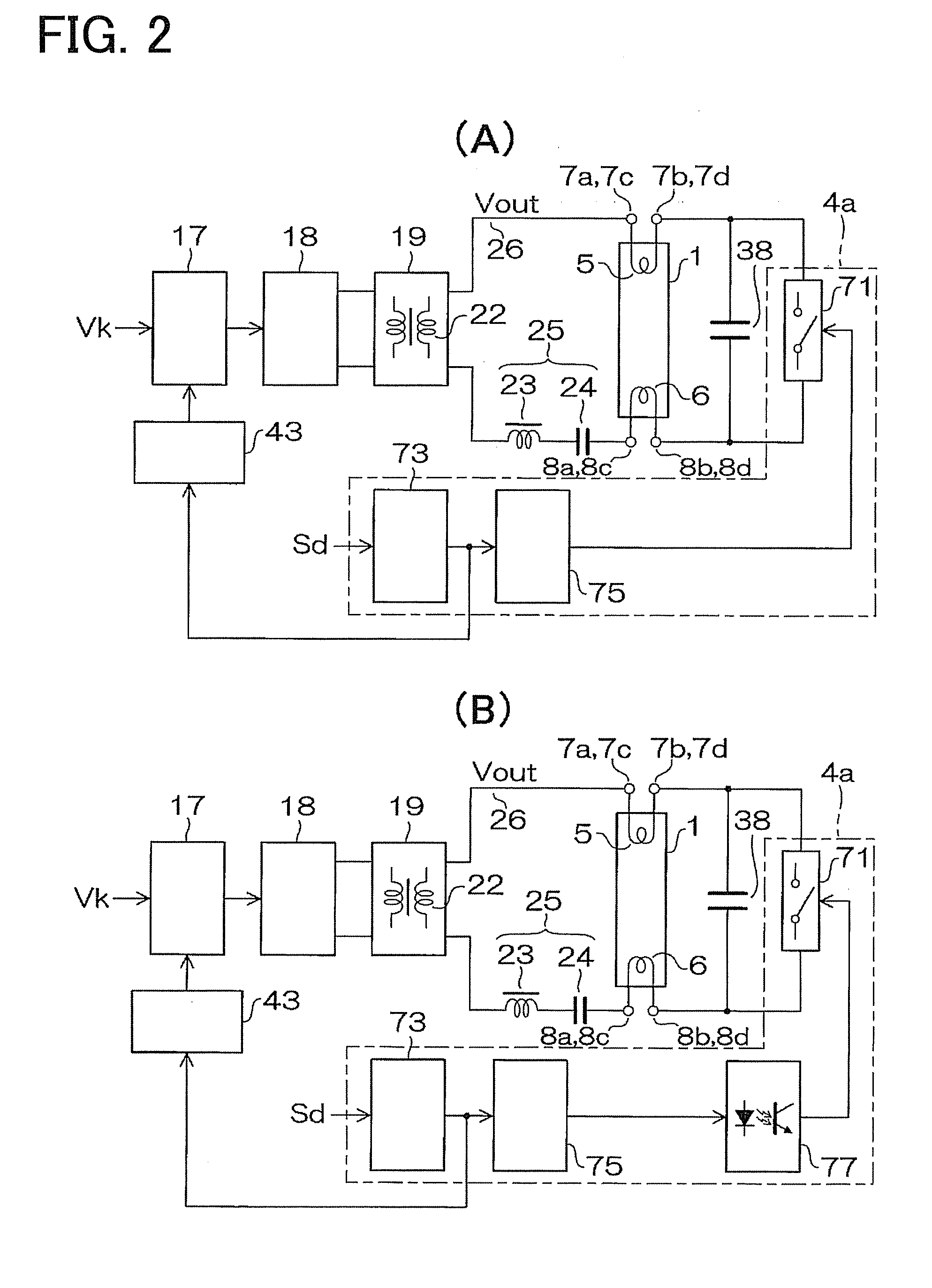
[0133]Next, the third embodiment is described, referring to FIG. 1 and FIG. 2 that extracted the component part about preheating control from the diagram in FIG. 1. In the fluorescent lamp drive 112, the fluorescent lamp 1, the input circuit unit 3, and the lighting control circuit unit 4 are the same as that of the first embodiment. The equivalent features are given the same mark as the corresponding elements in the first embodiment, and only the different features are explained in full detail.

[0134]Preheating Control Circuit Unit 4a

[0135]As shown in FIG. 2 (A), the preheating control circuit unit 4a comprises a switch 71, a preheating time setting circuit 73, and a switch drive circuit 75. The switch 71 is an analog switch which consists of switching elements, such as MOSFET, and it carries out on-off control according to the gate control signal inputted into a gate terminal.

[0136]As long as it can output and input bidirectionally and is constituted by the sem...


PUM


Abstract

An LED lighting circuit mounted in a lighting device having LEDs as a light source, the circuit including:
    • a light emitting unit that includes a plurality of LED circuits for supplying drive currents to a plurality of LEDs connected in series or parallel;
    • a failure detection unit that detects whether each of the drive currents flowing through the plurality of LED circuits is equal to or larger than a predetermined fault current value for those LED circuits as a whole; and
    • a failure alert unit that performs a predetermined alert operation if the failure alert unit detects that at least one of the drive currents is equal to or larger than the predetermined fault current value.

Description

BACKGROUND OF THE INVENTION[0001]1. Field of the Invention[0002]This invention relates to control of lighting fixtures, explaining in detail, a fluorescent lamp drive for controlling lighting of the fluorescent lamp, and the protection circuit of the fluorescent lamp drive.[0003]2. Description of the Related Art[0004]Conventionally, a fluorescent lamp (a fluorescent tube) 81 as shown in FIG. 23 has been used as an indoor light for such as railroads widely. The fluorescent lamp 81 is a light implement which lets the ultraviolet rays occurring by electric discharge into the phosphor in a tube and converts the rays into the visible light and outputs. A fluorescent lamp drive 82 that controls turning on and off of the fluorescent lamp 81 is connected to the fluorescent lamp 81. An inverter 83 and a transformer 84 is disposed in the fluorescent lamp drive 82. The fluorescent lamp drive 82 changes the inputted direct-current voltage into alternating current voltage with the inverter 83. T...

Claims


Application Information

Patent Timeline
IPC IPC(8): H05B37/03
CPCH05B33/0887Y02B20/341H05B41/2985H05B41/295H05B45/50Y02B20/30H05B47/28H05B47/25
Inventor SUMI, YOSHIKAZUTANASE, TAKUHIRO
Owner SANYO ELECTRIC WORKS LTD
Why Eureka
Try Eureka