
Method and apparatus for through the wall radar imaging

a radar imaging and wall technology, applied in the direction of reradiation, measurement devices, instruments, etc., can solve the problems of radar image degradation, inaccessible target imaging, and reduced power of both electromagnetic waves that impact the target,

Inactive Publication Date: 2012-09-20
TATOIAN JAMES Z +1
View PDF0 Cites 31 Cited by
  • Summary
  • Abstract
  • Description
  • Claims
  • Application Information

AI Technical Summary

Benefits of technology

[0027]The present invention comprises a method for through the wall radar imaging. In the present invention, an impulse synthetic aperture radar system (“ImpSAR™”) transmits short, ultra-wideband (“UWB”) carrierless microwave pulses at an obstacle behind which a target of interest is located. For each transmitted pulse, the return signals are received, stored and analyzed. Portions of the return signals that represent reflections from the obstacle are identified and analyzed in the time domain to estimate the transmission coefficient of the wall, either by estimating wa...

Problems solved by technology

Imaging of inaccessible targets is an important problem for a number of applications.
In TWRI, the interceding shielding obstacle causes a number of issues.
One is that the shielding obstacle reduces the power of both the electromagnetic waves that impact the target, as well as the waves that are reflected from the target back to the radar receiver.
Finally, the obstacle distorts the waveform that impinges on it and thus distorts the waveform received back at the receiver, which ultimately results in the radar image degradation.
In many circumstances, that will not be practical.
However, in a practical application, such as seeking to identify enemy agents inside a building, the wall characteristics will typically not be known.
A drawback of this system is that it requires access to the wall in question before the target in question.

Method used


Image

  • Method and apparatus for through the wall radar imaging
  • Method and apparatus for through the wall radar imaging
  • Method and apparatus for through the wall radar imaging

Examples


Embodiment Construction

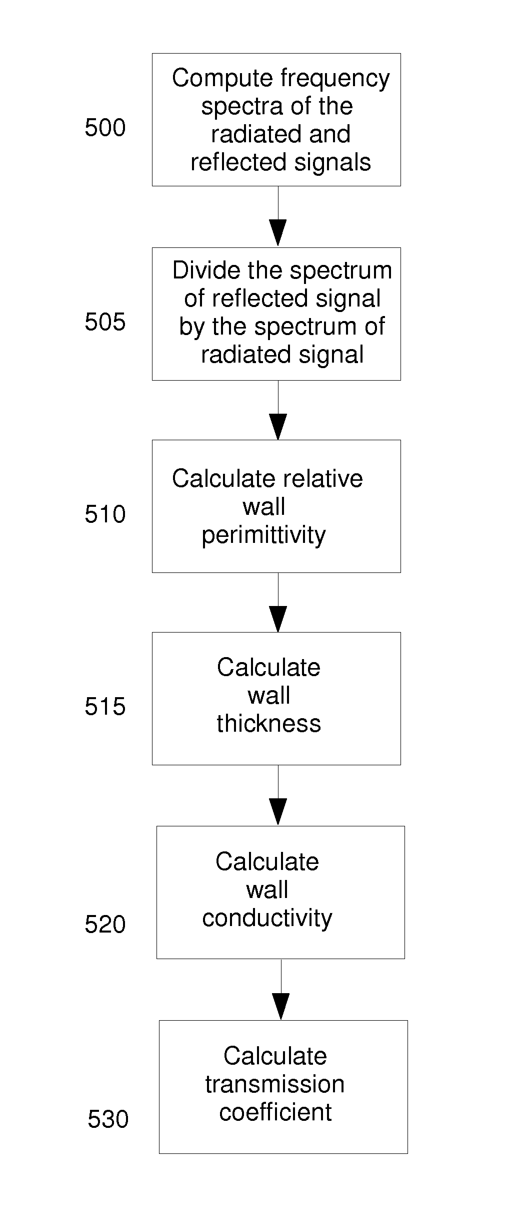
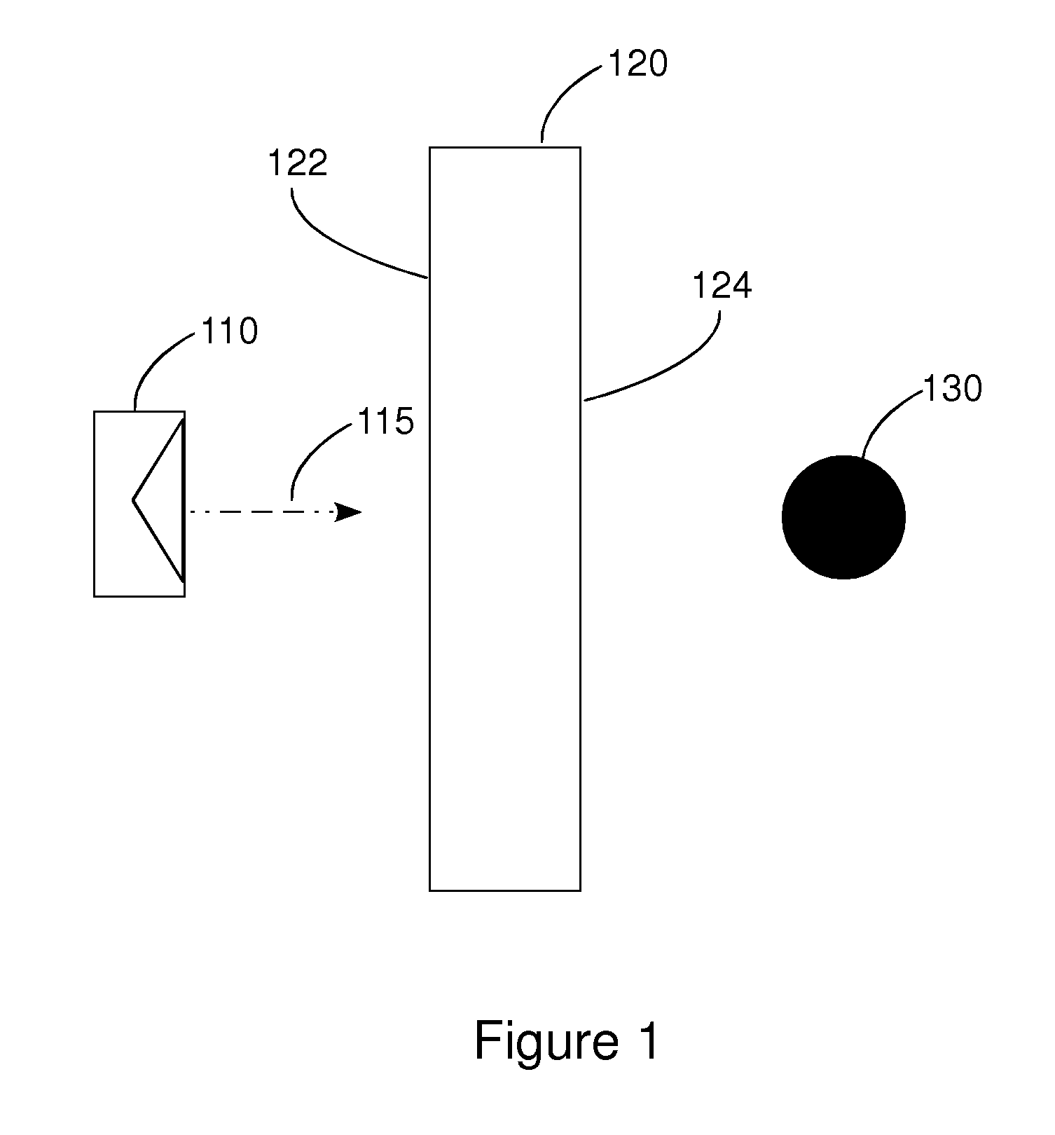
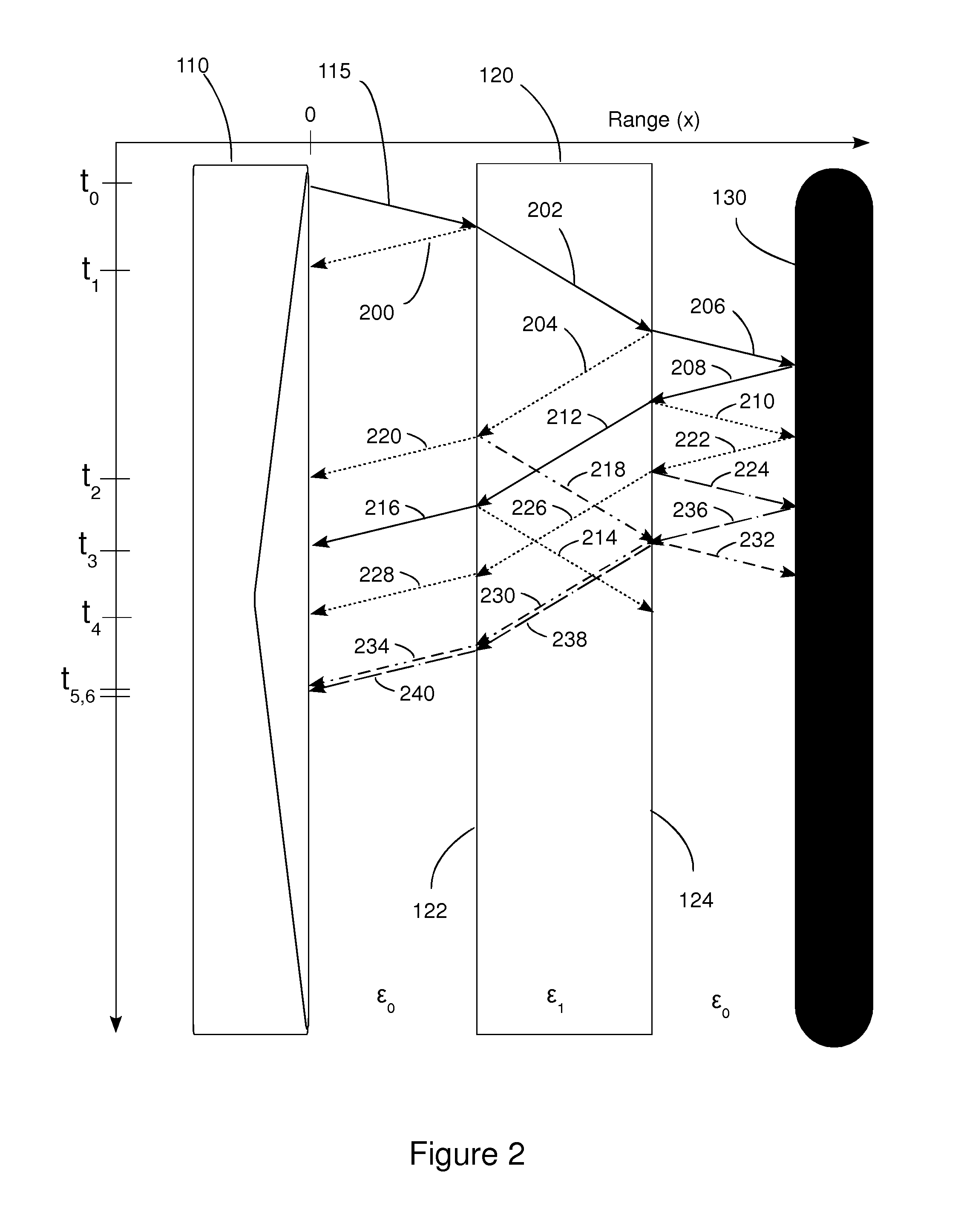
[0040]The present invention comprises a method for through the wall (or other obstacle) radar imaging. In the present invention, an impulse synthetic aperture radar system, such as, for example, an ImpSAR™ impulse synthetic aperture radar system from Eureka Aerospace, Inc., may be used. Synthetic aperture radar (“SAR”) is a known way to synthesize a long antenna (needed to obtain improved cross-range target resolution) by using a small element antenna moving in a rectilinear path, which could be parallel to the side of the wall. In an impulse SAR system, the signals that are transmitted by the antenna are short, carrierless UWB impulses. At each of a plurality of discrete positions along its movement, the element antenna radiates a UWB impulse toward the wall and records the received signal, scattered back by the wall and the inside target. The result, after processing of the signals received at each location, approximates using a much longer antenna array comprising a number of ele...


PUM


Abstract

The present invention comprises a method for through the wall radar imaging. An impulse synthetic aperture radar system transmits short, ultra-wideband carrierless microwave pulses at an obstacle behind which a target of interest is located. The return signals are received, stored and analyzed. Portions of the return signals that represent reflections from the obstacle are identified and analyzed in the time domain to estimate the transmission coefficient of the wall, either by estimating wall parameters or by using a novel shift and add procedure. The estimated transmission coefficient is used to filter the received signals to reduce the components of the received signal that are generated by the obstacle, and to compensate for distortion caused by the obstacle in the portions of the transmitted signal that are reflected by the target and returned, through the obstacle, to the radar system.

Description

CROSS-REFERENCE TO RELATED APPLICATION[0001]This patent application claims the benefit of the filing date of U.S. Provisional Patent Application No. 61 / 415,769 filed Nov. 19, 2010.BACKGROUND OF THE INVENTION[0002](1) Field of the Invention[0003]The present invention relates to a method and apparatus for through the wall imaging and in particular to a method and apparatus for through the wall imaging that comprises a novel method for compensating for the effects of a wall or other obstacle between a radar device and a target.[0004](2) Description of the Related Art[0005]Imaging of inaccessible targets is an important problem for a number of applications. Detection of people buried under the remnants of a building destroyed by an earthquake is a pertinent example. Investigation from outside the building of the presence of terrorists or hostages inside a room with shielded windows is another important application. A possible non-invasive imaging technique is the use of a radar system t...

Claims


Application Information

Patent Timeline
IPC IPC(8): G01S13/89
CPCG01S13/0209G01S13/888G01S13/90
Inventor TATOIAN, JAMES Z.FRANCESCHETTI, GIORGIO
Owner TATOIAN JAMES Z
Learn More