
Buffer Sizing for Multi-Hop Networks

a multi-hop network and buffering technology, applied in the field of networks, can solve problems such as application filling gaps, sub-utilization, and increased queuing delays

Active Publication Date: 2012-09-20
KING ABDULLAH UNIV OF SCI & TECH
View PDF2 Cites 25 Cited by
  • Summary
  • Abstract
  • Description
  • Claims
  • Application Information

AI Technical Summary

Benefits of technology

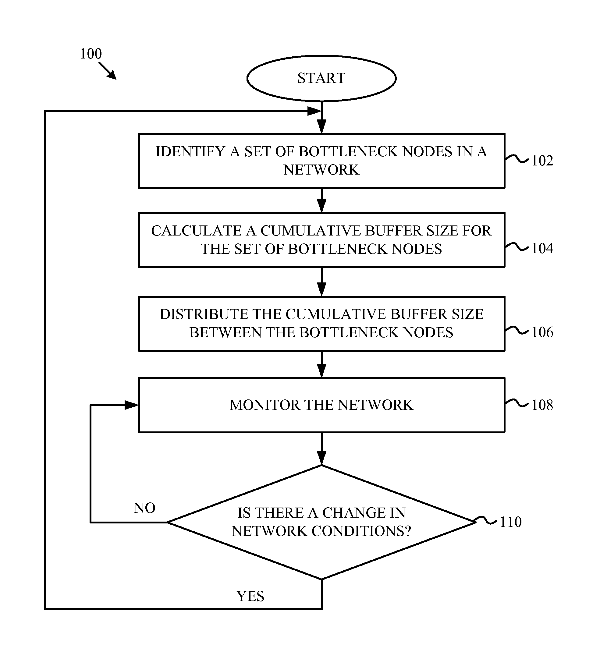
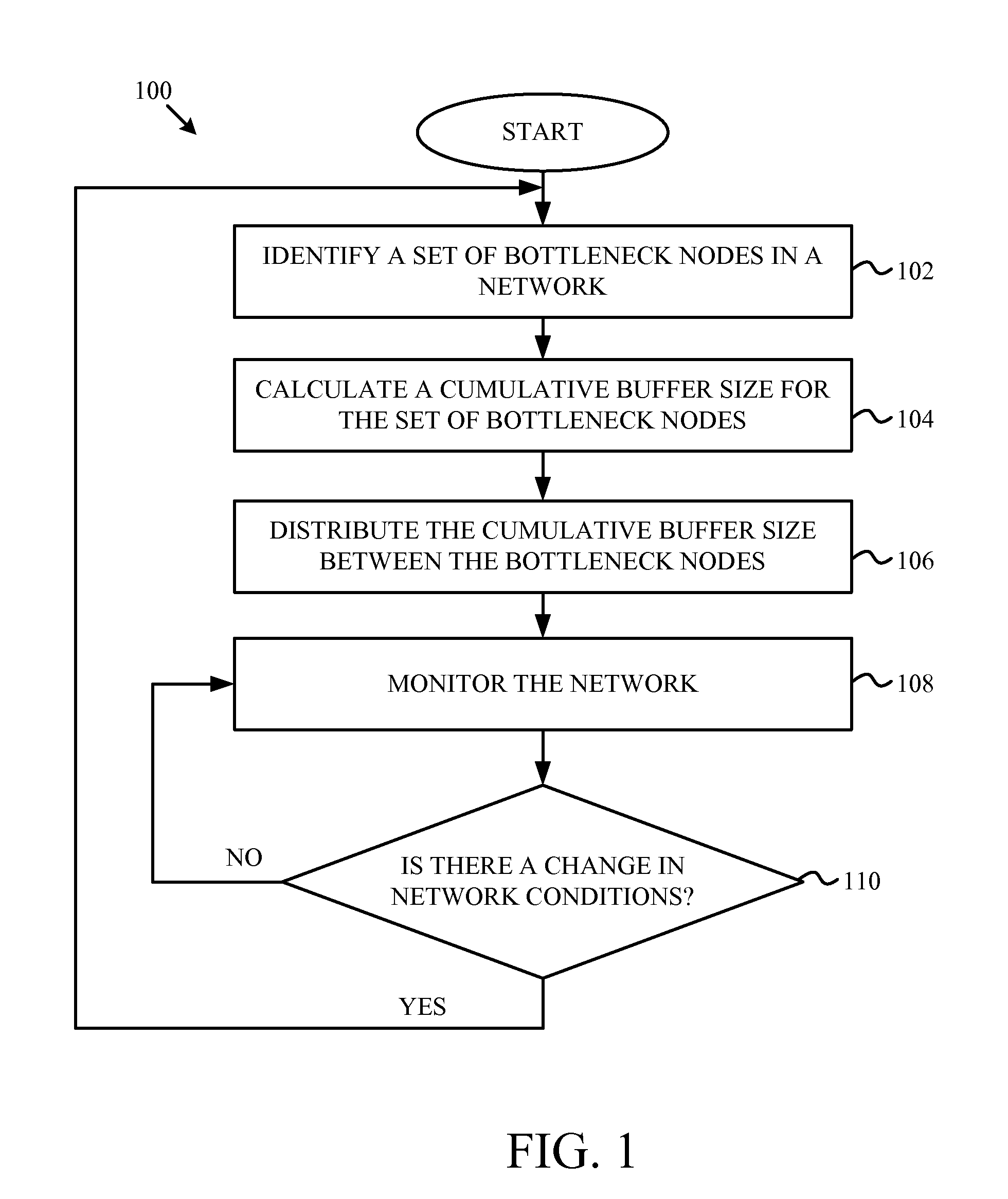
The patent describes a method for identifying bottleneck nodes in a wireless mesh network and distributing a cumulative buffer size among them. This helps to improve network performance and reduce interference between communication links. The patent also includes a computer program product and a system for implementing the method. The technical effects of the patent include improved network performance and reduced interference between communication links.

Problems solved by technology

Buffer sizing is an important network configuration parameter: under-buffered networks lead to frequent packet loss and subsequent under-utilization of network resources, and over-buffered networks lead to increased queuing delays.
Usually the application fills in gaps where data is either delayed, lost, or corrupted during its transmission through the network.
The end-to-end rate of this flow is limited by the link with the smallest available capacity along this path.
With declining memory chip prices, system architects may be inclined to over-provision routing buffers.
This, however, does not necessarily lead to improved network performance.
Large network buffers increase the delay before this congestion information can be communicated to the TCP source.
This may have a number of ramifications: first, it may affect the stability characteristics of the TCP stream, and second, it may impact the delay characteristics for other flows (both real-time and TCP) sharing the buffer with this stream.
The wireless domain introduces a number of new challenges in understanding the impact of buffer size on network performance.
Furthermore, the capacity of this shared spectrum is not a known constant, but varies over time due to sporadic noise and interference from other wireless nodes.

Method used


Image

  • Buffer Sizing for Multi-Hop Networks
  • Buffer Sizing for Multi-Hop Networks
  • Buffer Sizing for Multi-Hop Networks

Examples


Embodiment Construction

[0028]Various features and advantageous details are explained more fully with reference to the non-limiting embodiments that are illustrated in the accompanying drawings and detailed in the following description. Descriptions of well-known starting materials, processing techniques, components, and equipment are omitted so as not to unnecessarily obscure the invention in detail. It should be understood, however, that the detailed description and the specific examples, while indicating embodiments of the invention, are given by way of illustration only, and not by way of limitation. Various substitutions, modifications, additions, and / or rearrangements within the spirit and / or scope of the underlying inventive concept will become apparent to those skilled in the art from this disclosure.

[0029]A buffer sizing mechanism may improve the throughput of a network data stream and minimize the queuing delay. In contrast with wired networks, which are concerned with sizing the buffer along the...


PUM


Abstract

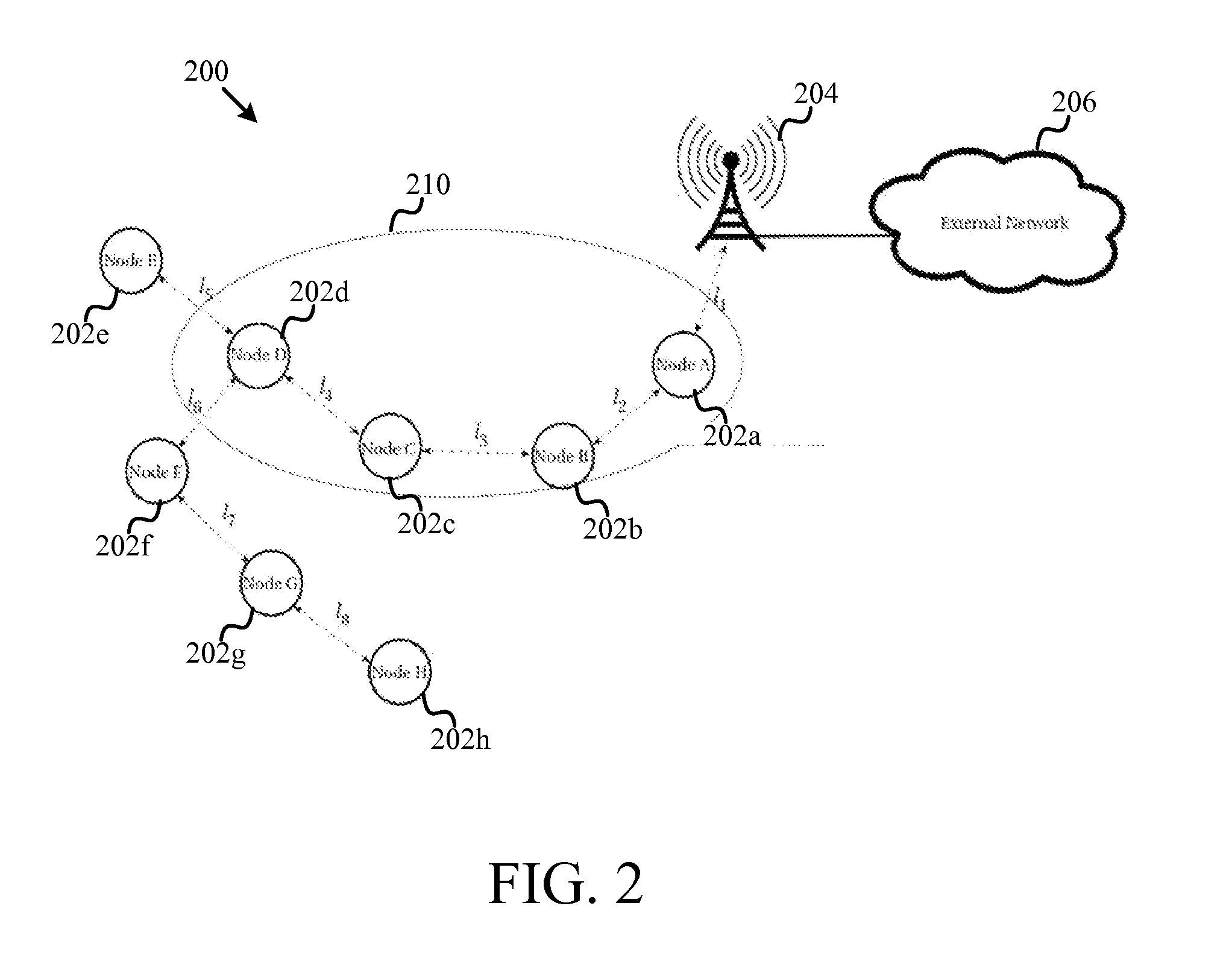
A cumulative buffer may be defined for an interference domain in a wireless mesh network and distributed among nodes in the network to maintain or improve capacity utilization of network resources in the interference domain without increasing packet queuing delay times. When an interference domain having communications links sharing resources in a network is identified, a cumulative buffer size is calculated. The cumulative buffer may be distributed among buffers in each node of the interference domain according to a simple division or according to a cost function taking into account a distance of the communications link from the source and destination. The network may be monitored and the cumulative buffer size recalculated and redistributed when the network conditions change.

Description

CROSS-REFERENCE TO RELATED APPLICATION[0001]This application claims priority to U.S. Provisional Patent Application No. 61 / 454,536 filed on Mar. 20, 2011, the entire contents of which is specifically incorporated by reference herein without disclaimer.BACKGROUND OF THE INVENTION[0002]1. Field of the Invention[0003]This invention relates to networks and more particularly relates to buffering of data when routing data in networks.[0004]2. Description of the Related Art[0005]Wireless mesh networks (WMNs) are a type of ad hoc wireless networks that uses multi-hop wireless communications to provide or improve connectivity between mesh routers. The mesh routers may be mobile or stationary. Client devices may connect to their preferred mesh router using wired or wireless technologies. The client traffic is then routed across the mesh from mesh router to mesh router to reach another device within the mesh. Alternatively, the client traffic is routed to an external device accessible via a ga...

Claims


Application Information

Patent Timeline
Patent Type & Authority Applications(United States)
IPC IPC(8): H04L12/26
CPCH04L43/0852H04L47/12H04L47/10H04L47/17H04L49/9005H04L47/14H04W84/18H04W28/021H04L47/18H04L47/283H04L47/30
Inventor SHIHADA, BASEMJAMSHAID, KAMRAN
Owner KING ABDULLAH UNIV OF SCI & TECH
Learn More