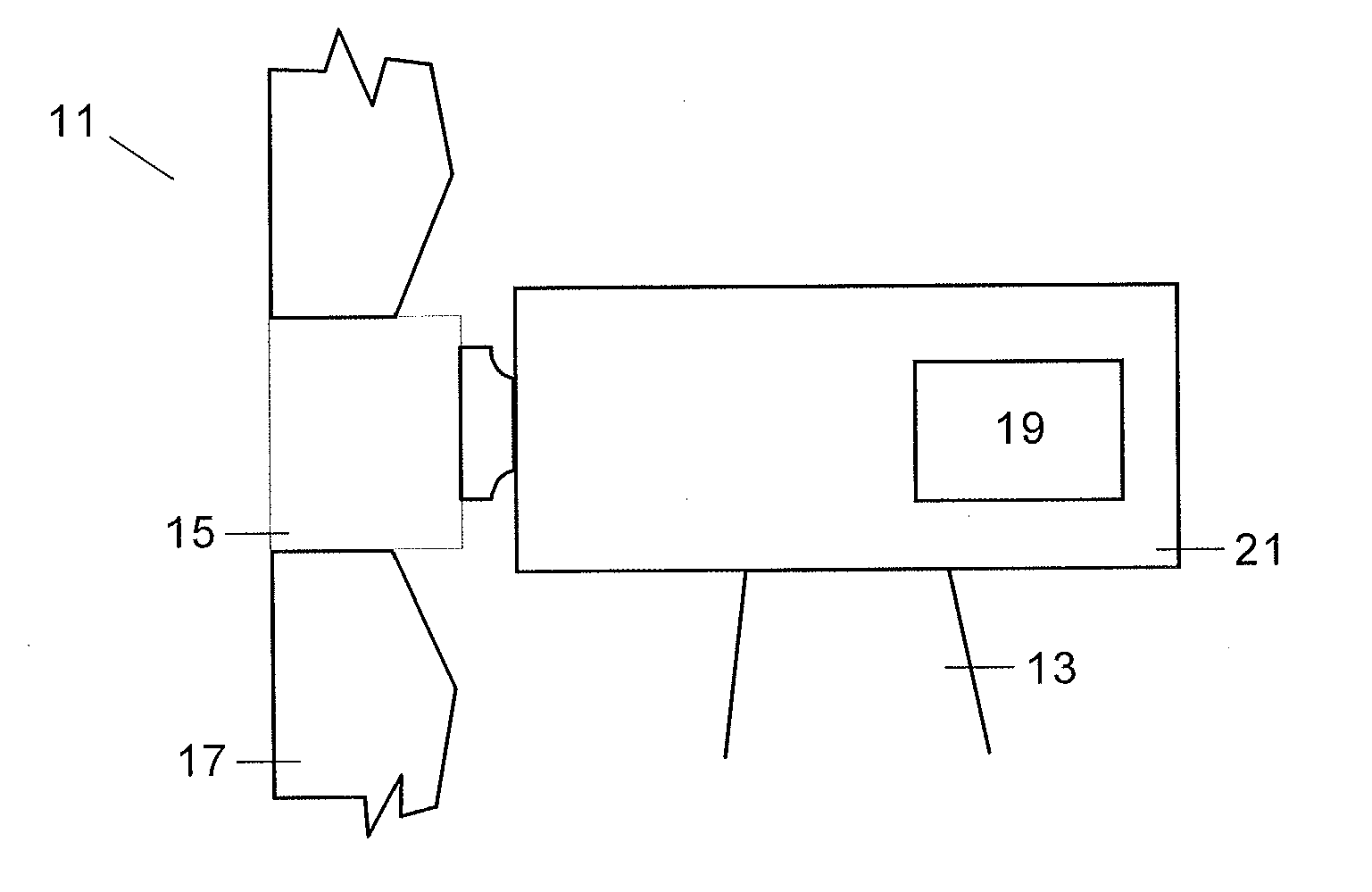
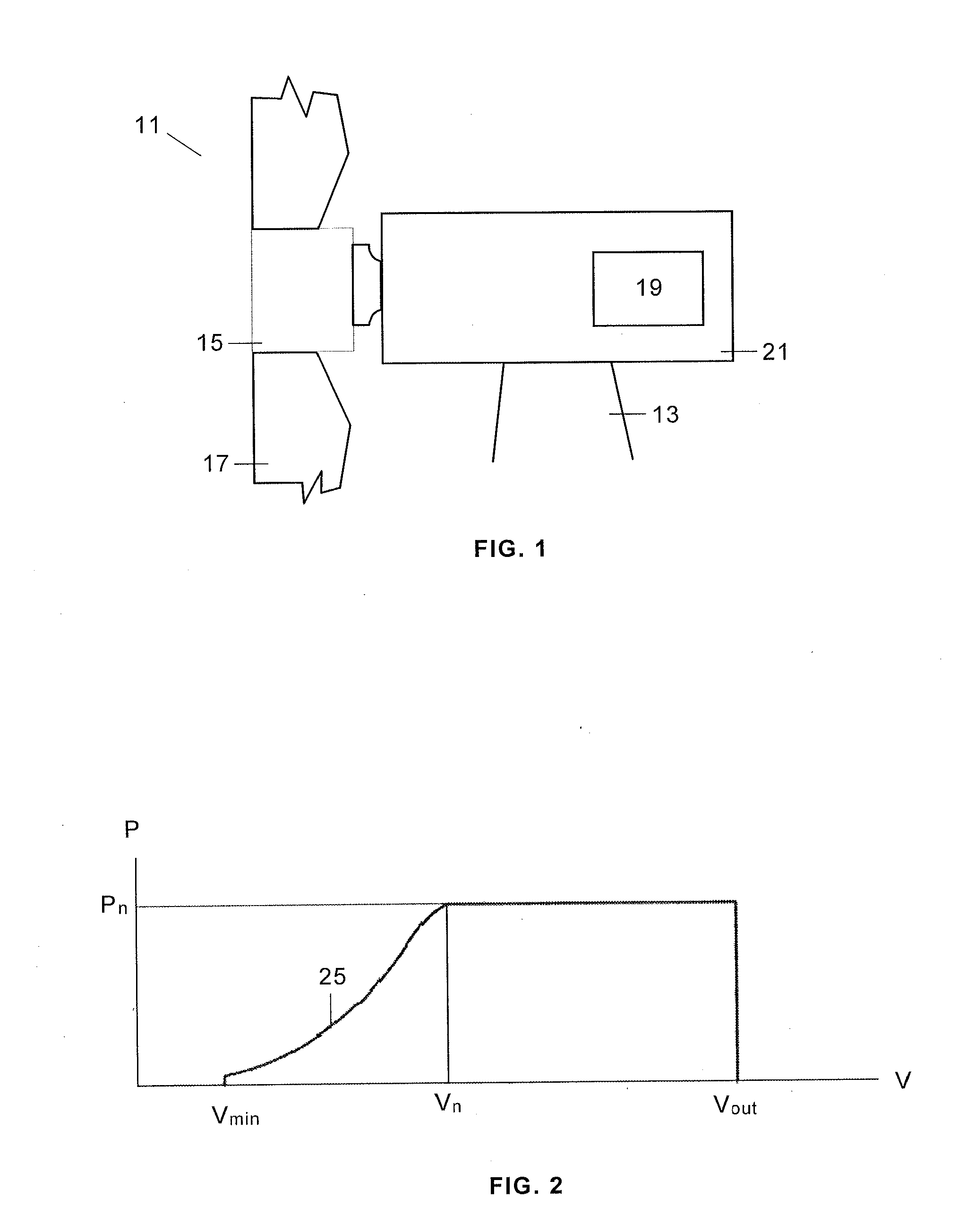
[0028]A typical wind turbine 11 comprises a tower 13 supporting a nacelle 21 housing a generator 19 for converting the rotational energy of the wind turbine rotor into electrical energy. The wind turbine rotor comprises a rotor hub 15 and, typically, three blades 17. The rotor hub 15 is connected either directly or through a gearbox to the generator 19 of the wind turbine for transferring the torque generated by the rotor 15 to the generator 19 and increase the shaft speed in order to achieve a suitable rotational speed of the generator rotor.
[0029]The wind turbine power output is typically controlled by means of a control system for regulating the pitch angle of the rotor blades and the generator torque. The rotor rotational speed and power output of the wind turbine can hereby be initially controlled.
[0030]Below the cut-out wind speed Vout the wind turbine control system is arranged to regulate the power production according to a curve which defines the desired functional relationship between power and speed to achieve ideal output. A curve of this type is curve 25 in FIG. 2 showing that the power production P increases from a minimum wind speed Vmin to the nominal wind speed Vn and then remain constant in the nominal power value Pn up to the cut-out wind speed Vout where decreases up to 0.
[0031]For implementing said regulation a control unit receives input data such as wind speed V, generator speed Ω, pitch angle θ, power P from well known measuring devices and send output data to, respectively, the pitch actuator system for changing the angular position of the blades 17 and to a generator command unit for changing the reference for the power production.
[0032]According to the present invention the control system is also arranged for applying an individual pitch control for reducing the asymmetric loads that does not use any measurement of the forces or moments acting on the wind turbine. This individual pitch control is superimposed to the conventional pitch control used for regulating the power production according to the power curve 25 of FIG. 2.
[0033]The basic ideas of the invention are the following: [0034] Determining the asymmetric loads using wind data as well as physical features of the wind turbine such as the position of the first bearing of the low speed shaft (for determining for example loads due to the rotor weight). Therefore for the determination of the asymmetric loads it is not used any measurement of its effects in the blades or any other component of the wind turbine, such as for example the bending moment on the root of the blades or the deflection of the low speed shaft. [0035] Providing a control law defining a cyclic pitch control for each individual blade that counteracts the effect of the considered drivers of asymmetric loads. An example of a control law according to the present invention is illustrated in FIG. 3. The line 31 represents the collective pitch applied to all the blades, i.e. a constant pitch along one blade revolution, and the line 33 represents a periodic pitch applied to one blade along a blade revolution resulting of adding the pitch according to said control law to the collective pitch. [0036] Implementing said control law in the wind turbine control means.
[0037]A further explanation of the invention follows.
[0038]Asymmetric Loads
[0039]The drivers of asymmetric loads considered in the present invention are the following: [0040] Wind shear which can be defined by a statistical value at the wind turbine site (for example a wind shear coefficient α of 0.2) or by a real-time value determined using wind data available at the wind turbine. If needed the statistical mean value can be changed for a better adaptation to the wind conditions at the wind turbine site. [0041] Upflow which can be defined by a statistical value at the wind turbine site (for example γz=8 degrees) or by a real-time value determined using wind data available at the wind turbine. If needed the statistical mean value can be changed for a better adaptation to the wind conditions at the wind turbine site. [0042] Yaw misalignment. Within the meaning of this invention yaw misalignment γy shall be understood as a misalignment smaller than the operating limit of the yaw control system. It is measured from the wind vane available at the wind turbine. [0043] Rotor weight. The self-weight of the rotor is a constant contribution acting on the fixed frame of reference, loading the structure with a constant valued moment. When the rotating frame is analyzed, this contribution is transformed into a fluctuation with frequency 1P (one rotor revolution), that generates a high level of fatigue, for example on the shaft. A cyclic pitch action can cancel out the effect of the self-weight by adding the corresponding aerodynamic counter-moment.
[0044]Control Law
[0045]The basic control law according to the present invention is the cyclic law included in the following equation:
θ=θ0+θc cos ψ,+θssen ψ Eq. 1
[0046]The pitch θ applied to any of the blades is therefore the sum of the collective pitch contribution θ0, plus a cyclic contribution on the instantaneous azimuth position ψ defined by the cosine and sine parameters θc and θs respectively.
[0047]Using the following notation:
[0048]θ0 Collective pitch command
[0049]Ω Rotor Speed
[0050]V Wind Speed
[0051]α Wind Shear
[0052]γy Yaw Misalignment
[0053]γz Upflow
[0054]an algebraic relationship between said parameters θc and θs and the current operating conditions at the wind turbine—including external wind conditions—can be defined as follows:
{ θ c θ s } = - { f c ( θ 0 , λ ; α , γ y , γ z ; … ) f s ( θ 0 , λ ; α , γ y , γ z ; … ) } Eq . 2
[0055]In an embodiment of the present invention said algebraic relationship can be derived employing the linearized flapping equation of motion and Coleman transformation. In this case, three equations are obtained for the out of plane bending moment (constant contribution, cosine fluctuation and sine fluctuation). By cancelling out the cosine and sine like fluctuations, or alternatively equating them to a prescribed value—e.g. for the cancellation of the rotor self-weight—the corresponding cyclic loads are obtained.
[0056]The control law is derived from the flapping equation of motion for one blade:
IΩ2({umlaut over (ζ)}+v2ζ)=(M0Mζζ+M{dot over (ζ)}{dot over (ζ)}+Mθθ+Mλλ+λMαα) Eq. 3
[0057]where [0058] I Flapping inertia [0059] ζ Flapping motion [0060] v Flapping motion eigen frequency [0061] M0 Constant flap bending moment [0062] Mx Derivative of flap bending moment with respect to variable x [0063] α Wind shear [0064] θ0 Collective pitch angle [0065] λ Tip Speed Ratio
[0066]The contributions of all the blades are summed by use of the Coleman transformation and the cyclic contributions are set to zero. Using a linearized aerodynamic model, the following relations are obtained.
{ θ c θ s } = - 1 M θ [ 2 3 R M rotor gx I ζ Ω 2 { - 1 N * } + { μ y μ z } ( M 0 + M λ λ + 2 T θ θ 0 ) λ { - R H α M θ 0 } + { - μ z μ y } M ζ 0 ζ 0 ] Eq . 4
[0067]where the effect of self-weight has been included, and the following parameters are employed: [0068] Mrotor Rotor mass [0069] g Gravity [0070] x Desired shaft position for zero bending moment (x=0: hub center) [0071] N* Phase Lag value (coupling originated by the precession terms) [0072] Tθ Thrust derivative with respect to pitch [0073] Mθ Out of plane bending moment derivative with respect to pitch [0074] Mλ Out of plane bending moment derivative with respect to tip speed ratio [0075] R Rotor radius [0076] H Tower height [0077] ζ0 Average flap deflection [0078] μy Lateral dimensionless wind speed=λ tan(−wnddir) [0079] λz Vertical dimensionless wind speed=λ tan(upflow)
[0080]In the case of the above mentioned FIG. 3 the control law corresponds to a typical wind turbine operating at a condition of a wind speed v=15 mps. The calculation has been performed for standard conditions (upflow γz=8 deg, wind shear α=0.2, yaw misalignment γy=0 deg) and the results obtained using Eq. 4 were θc=0.78 deg and θs=0.17 deg. For steady operation the out of plane bending moment standard deviation is reduced to 40% of the case without the cyclic contribution.
[0081]In an embodiment of the present invention the control law includes additional terms in order to reduce the 3P oscillations in the non-rotating frame (which are counteracted by 2P oscillations in the rotating frame). In this case, the control law is the cyclic law included in the following equation:
θ=θ0+θc cos ψ+θs sin ψ+θc3P cos 2ψ+θs3P sin 2ψ=θ0+(θc+θc3P cos 3ψ+θs3P sin 3ψ)cos ψ+(θs+θc3P sin 3ψ−θs3P cos 3ψ)sin ψ Eq. 5
[0082]Introducing this expression in the formulation, additional terms appear.
1 8 { θ c 3 P θ s 3 P } = - { A + C B + D } A = 1 6 ( - μ z θ s + μ y θ c ) B = 1 6 ( μ z θ c + μ y θ s ) C = λ R H α 1 12 μ y ( - 1 ) D = λ R H α 1 12 μ z ( - 1 )
[0083]FIG. 4 illustrates the two mentioned embodiments of the present invention: a control law with 1P functions (circle 33) and control law with 1P and 2P functions (circle 35). Both control laws are the result of adding a cyclic pitch to the collective pitch θ0 which is represented in circle 31 as a constant pitch along one blade revolution.
[0084]The difference between control laws 31 and 33 is that the first is a periodic function with a frequency equal to the rotor rotation frequency and the second superimposes on this basic law another contribution with a frequency equal to two times the rotor frequency, aimed at minimizing the loads transmitted at this frequency to the structure.
[0085]Implementation
[0086]The implementation of a control law according to this invention is done upon the typical wind turbine controller, including the additional pitch contribution after the collective signal generation is determined by the controller. The collective contribution is still the standard pitch reference for the controller regarding alarms and operation set points. The dependence of the control law with the operation region is provided to the controller as a function of the collective pitch angle. As it has already been said the environmental conditions are provided in terms of wind shear, upflow, wind speed and horizontal wind direction to the control unit where said additional pitch contribution is determined using the above-mentioned equations. The values of the inertial and aerodynamic terms associated to the wind turbine included in said equations are provided to said control unit by any suitable means.
[0087]The additional pitch action generated by a control law according to this invention may be restricted to certain limit values and operation regions in order to avoid potential performances degradation.
[0088]Advantages
[0089]The main advantages of the cyclic pitch control according to the present invention are the following: [0090] It provides a reduction of the damaging effects of asymmetric loads at a low cost because it does not require any hardware modification. [0091] It can be easily implemented in those wind turbines already in operation with individual pitch actuation systems but lacking an individual pitch action for counteracting asymmetric loads. [0092] It can be also implemented in those wind turbines provided with an individual pitch control system for asymmetric load reduction using load measurements to act as back-up system when said individual pitch control system is not operative due to, for example, failures in the load measuring devices. The wind turbine could then continue operating in a normal mode without a power reduction.
[0093]Of course the methods and systems according to this invention using wind standard conditions will not be as effective in the load alleviation as those methods and systems based on individual pitch control that use load measurements for calculating the individual pitch action but offers a potentially consistent reduction employing less pitch activity. Using real-time wind data the results will be comparable to load measuring methods.
[0094]Although the present invention has been fully described in connection with preferred embodiments, it is evident that modifications may be introduced within the scope thereof, not considering this as limited by these embodiments, but by the contents of the following claims.