Magnetic recording medium
a recording medium and magnetic technology, applied in the field of magnetic recording mediums, can solve the problems of difficult to transmit heat from the highly thermally conductive thin film side, difficult to accurately heat the recording track, and difficult to record information on the disk, etc., to achieve accurate orientation, effective heating, and stable recording. easy
- Summary
- Abstract
- Description
- Claims
- Application Information
AI Technical Summary
Benefits of technology
Problems solved by technology
Method used
Image
Examples
first embodiment
[0051]Hereinafter, a first embodiment of a magnetic recording medium in the present embodiment will be described based on the drawings. In addition, in the respective drawings used in the description as below, the scale is appropriately changed in order to make each member a recognizable size.
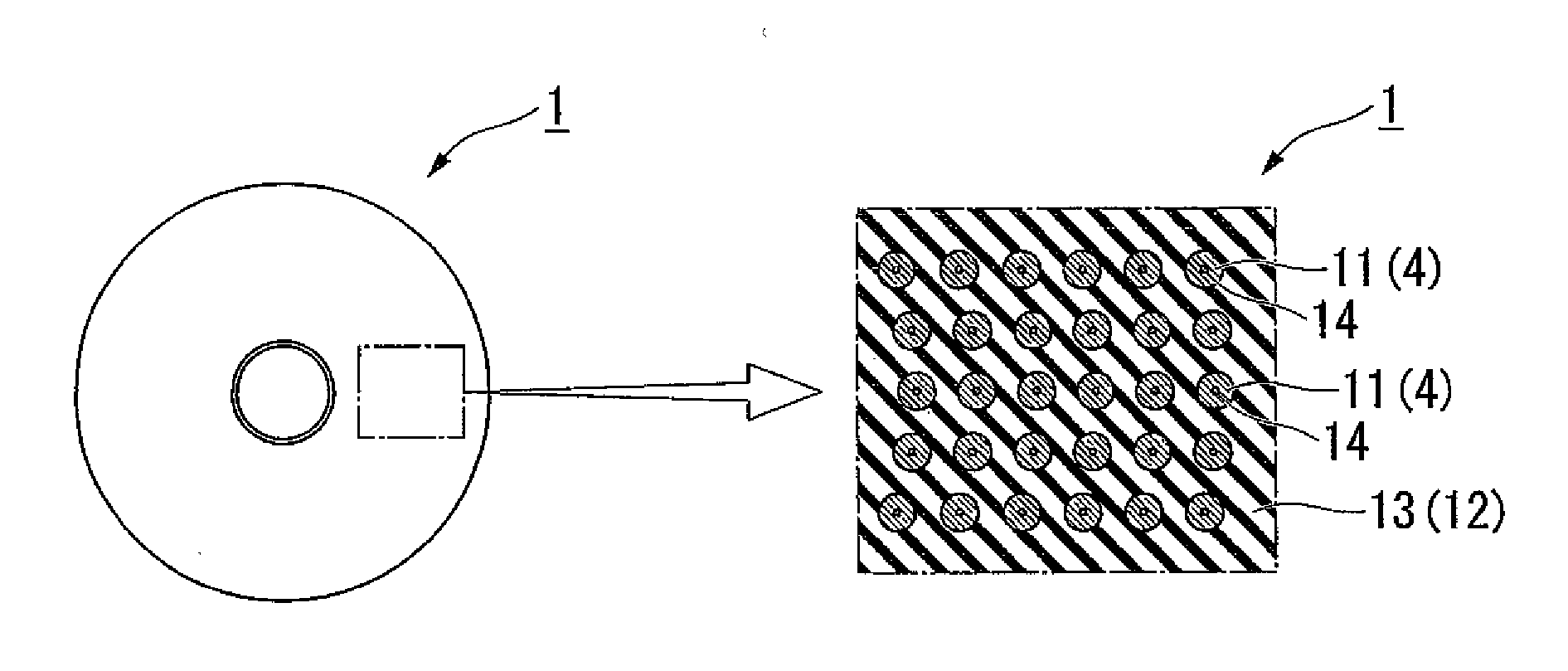
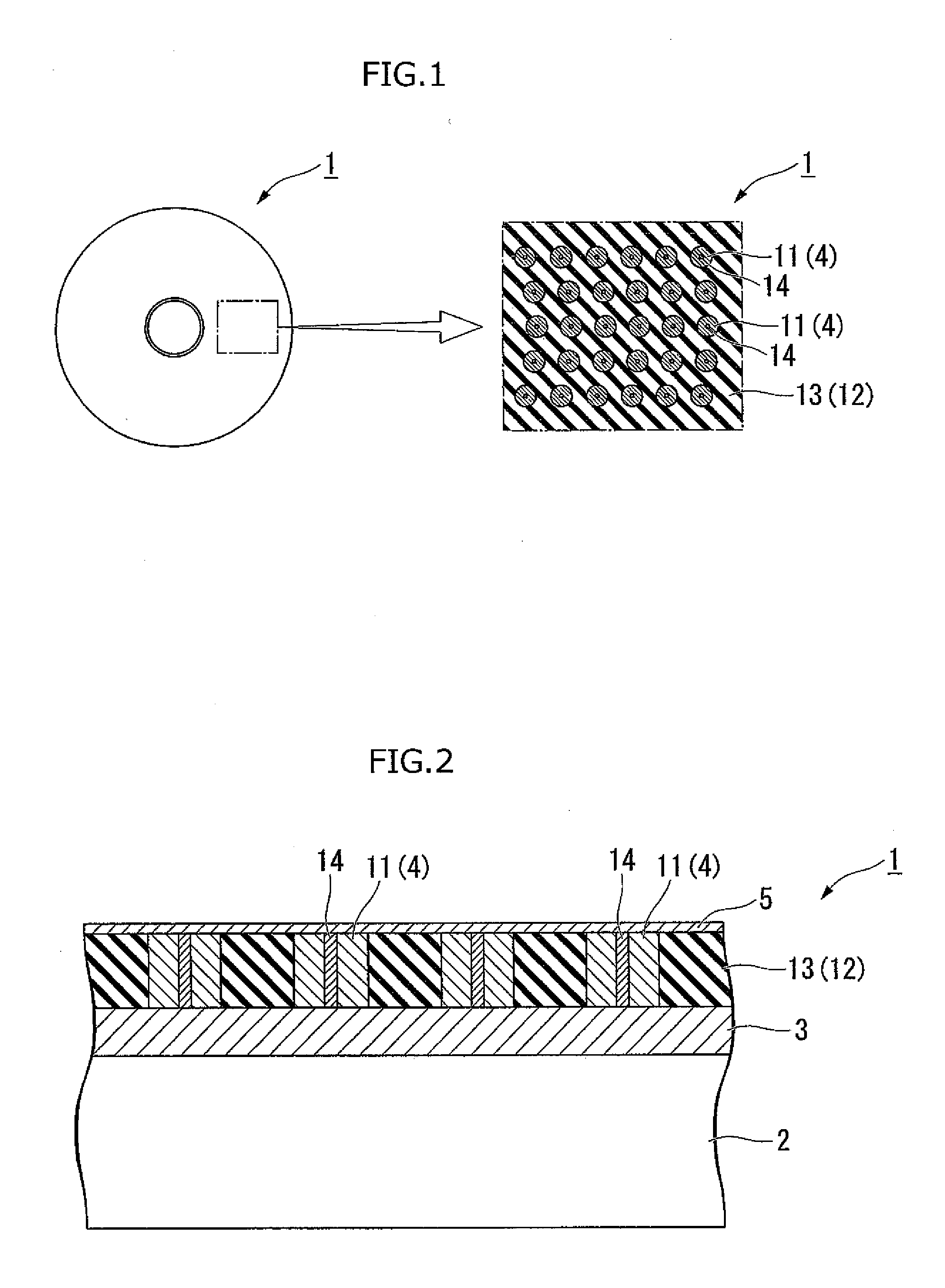
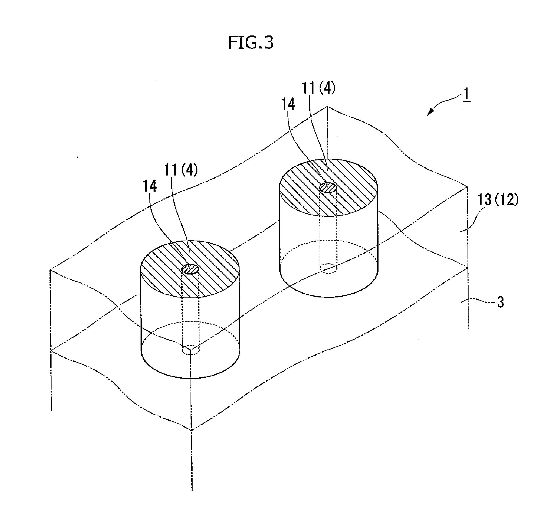
[0052]As shown in FIG. 1, a magnetic recording medium 1 in the present embodiment forms a disk shape when viewed from an upper surface, and as shown in FIGS. 2 and 3, includes a substrate 2, a ground layer 3 formed on the substrate 2, a recording layer 4 formed on the ground layer 3, and a protective layer 5 formed on the recording layer 4. In addition, in a partially enlarged view of FIG. 1 and FIG. 3, the protective layer 5 is removed. Furthermore, in the present embodiment, a direction perpendicular to a center axis of the magnetic recording medium 1 forming the disk shape when viewed from the upper surface is the radial direction, and a direction around the center axis is the circumferentia...
second embodiment
[0074]Next, a second embodiment of the magnetic recording medium in the present invention will be described based on the drawings. In addition, a basic configuration of the embodiment described herein is the same as that of the first embodiment mentioned above, and other elements are added to the first embodiment mentioned above. Thus, in FIG. 7, the same components as those of FIGS. 1 to 6D are denoted by the same reference numerals, and the descriptions thereof will be omitted.
[0075]As shown in FIG. 7, in a magnetic recording medium 50 of the present embodiment, a high thermal conductor 51 comes into contact with the substrate 2 through the recording layer 4 and the ground layer 3.
[0076]According to the magnetic recording medium 50 of the configuration as mentioned above, since a contact area between the high thermal conductor 51 and the ground layer 3 can be sufficiently ensured, the heat is easily transmitted from the recording layer 4 heated via the high thermal conductor 51 to...
third embodiment
[0077]Next, a third embodiment in the present invention will be described based on the drawings. In addition, a basic configuration of the embodiment described herein is the same as that of the second embodiment mentioned above, and other elements are added to the second embodiment mentioned above. Thus, in FIG. 8, the same components as those of FIG. 7 are denoted by the same reference numerals, and the descriptions thereof will be omitted.
[0078]As shown in FIG. 8, in a magnetic recording medium 60 of the present embodiment, a high thermal conductor 61 forms a circular truncated cone shape. That is, a cross-sectional area of a direction perpendicular to a stacking direction of the magnetic recording medium 60 in the high thermal conductor 61 is increased as facing the substrate 2 in the stacking direction.
[0079]According to the magnetic recording medium 60 of the configuration as mentioned above, since a contact area between the high thermal conductor 61 and the ground layer 3 is i...
PUM
 Abstract
Description
Claims
Application Information
 - R&D
- Intellectual Property
- Life Sciences
- Materials
- Tech Scout
- Unparalleled Data Quality
- Higher Quality Content
- 60% Fewer Hallucinations
Browse by: Latest US Patents, China's latest patents, Technical Efficacy Thesaurus, Application Domain, Technology Topic, Popular Technical Reports.
© 2025 PatSnap. All rights reserved.Legal|Privacy policy|Modern Slavery Act Transparency Statement|Sitemap|About US| Contact US: help@patsnap.com


