Device and method for regulating an energy recovery in a pedal-driven vehicle

a technology of energy recovery and pedal drive, which is applied in the direction of braking system, process and machine control, instruments, etc., can solve the problems of jolting and difficult switching between energy recovery and friction brake, and no energy is recovered for charging the batteries

Inactive Publication Date: 2012-09-20
ROBERT BOSCH GMBH
View PDF3 Cites 24 Cited by
  • Summary
  • Abstract
  • Description
  • Claims
  • Application Information

AI Technical Summary

Benefits of technology

[0012]Moreover, the vehicle preferably also includes a velocity sensor for detecting the instantaneous velocity of the vehicle. With the help of a vehicle's instantaneous velocity value, the control unit may be configured in such a way, for example, that the energy recovery is terminated when the vehicle is bra...

Problems solved by technology

In this process, changing between the energy recovery and a friction brake is jolting and difficult, because of manual switching.
For this reason, the energy recovery of t...

Method used


Image

  • Device and method for regulating an energy recovery in a pedal-driven vehicle
  • Device and method for regulating an energy recovery in a pedal-driven vehicle

Examples


Embodiment Construction

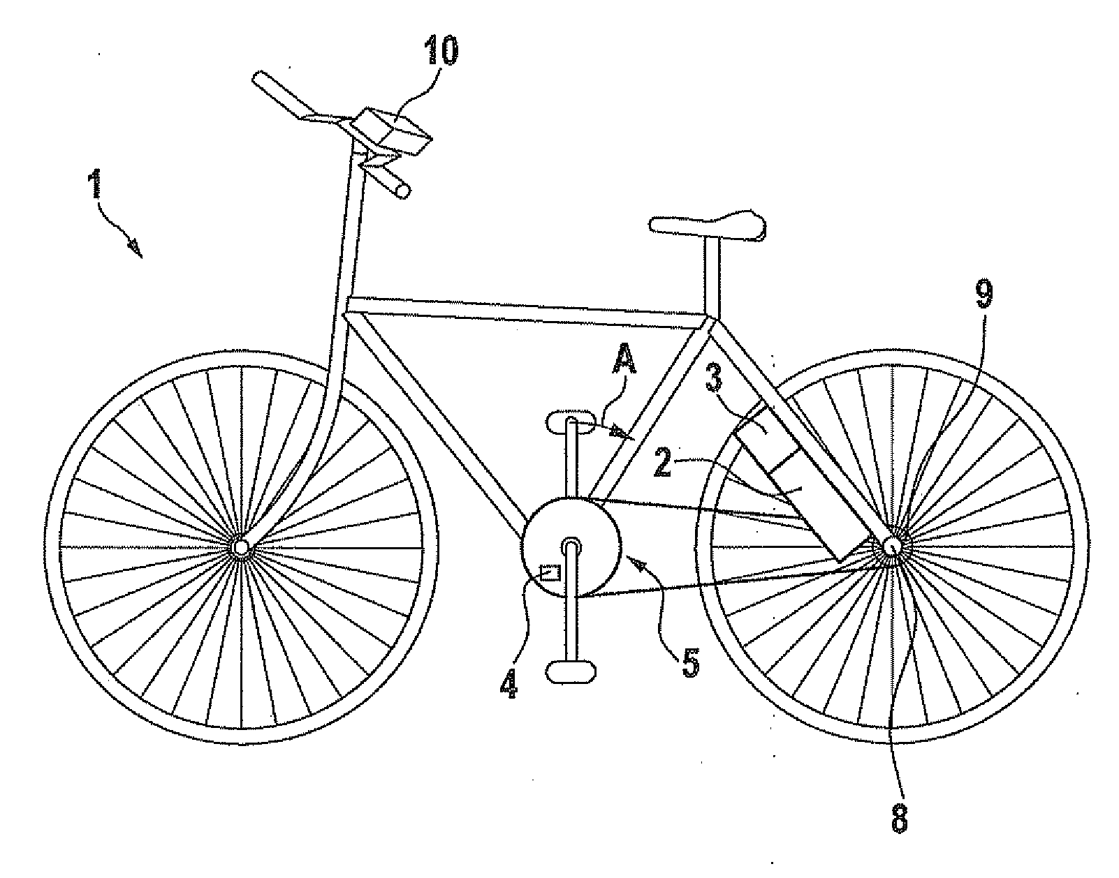
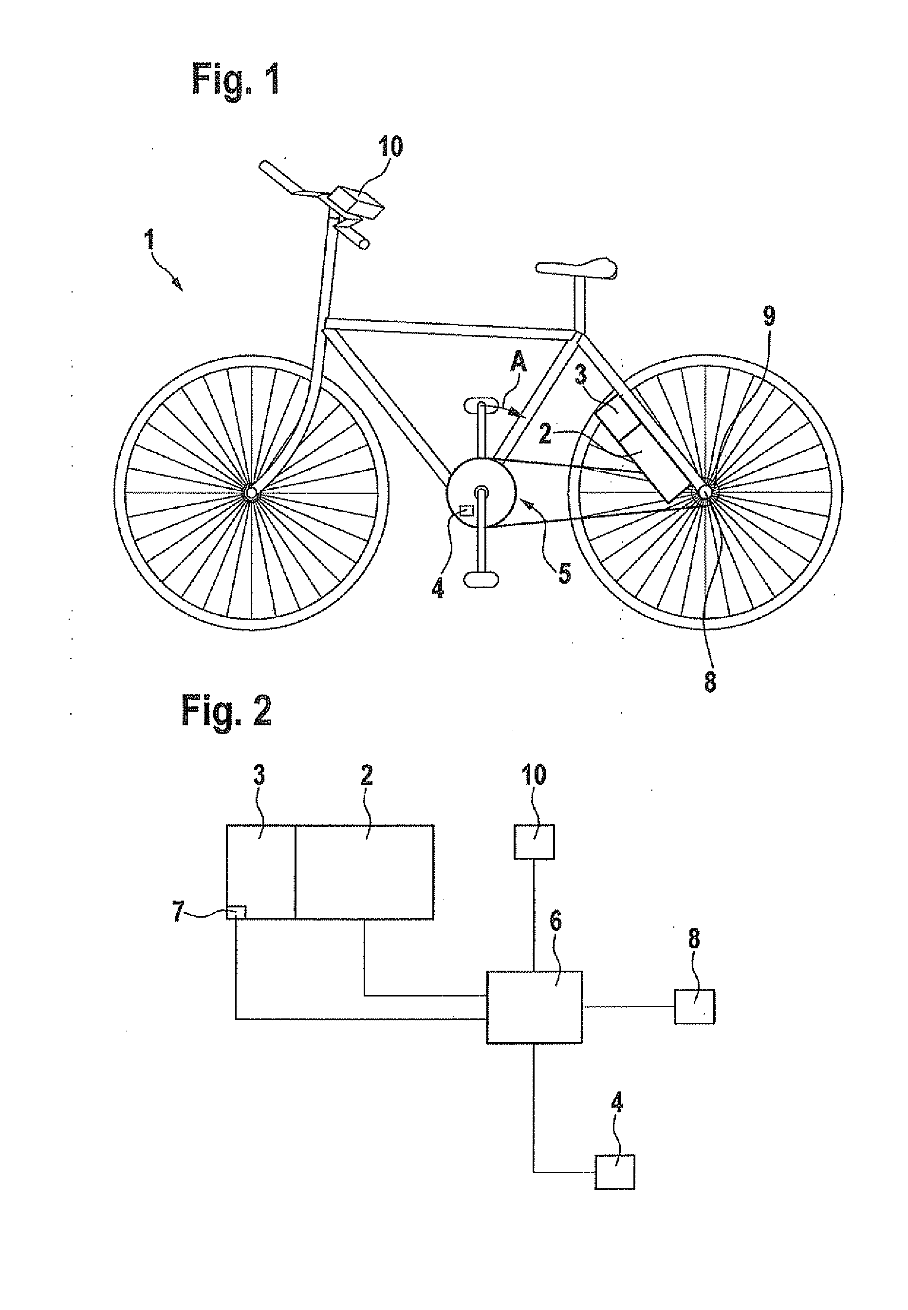
[0015]In the following, a vehicle according to one preferred exemplary embodiment of the present invention will be described in greater detail with reference to FIGS. 1 and 2. As is apparent in FIG. 1, the vehicle in this exemplary embodiment is a bicycle 1. Bicycle 1 has an auxiliary drive that includes an electric auxiliary drive 2, a rechargeable battery 3 and a control unit 6. Electric auxiliary drive 2 is preferably a compact electric motor having an integrated gear, in particular a planetary gear. The auxiliary drive further includes a direction of rotation sensor 4, which is located at a crank drive 5 of the bicycle. Direction of rotation sensor 4 detects the direction of rotation of crank drive 5, i.e., a direction of rotation forward, or a direction of rotation backward. If direction of rotation sensor 4 does not send a signal to control unit 6, this means that the crank drive is momentarily not being operated. Moreover, a velocity sensor 8 is provided, which detects the in...


PUM


Abstract

A method for regulating an energy recovery in a pedal-driven vehicle having a crank drive, an electric auxiliary drive and a rechargeable energy source includes: detecting a direction of rotation of the crank drive, and recovery of energy and storage of energy in the energy source when the direction of rotation of the crank drive is directed backward.

Description

BACKGROUND OF THE INVENTION[0001]1. Field of the Invention[0002]The present invention relates to a device and a method for regulating an energy recovery in a pedal-driven vehicle such as, for example, a bicycle.[0003]2. Description of Related Art[0004]Various designs of bicycles having an electric auxiliary motor are known from the related art. These types of bicycles usually have a manually operable control unit on the handlebar with the aid of which an electric auxiliary drive may be switched on, or which makes energy recovery possible. In this process, changing between the energy recovery and a friction brake is jolting and difficult, because of manual switching. For this reason, the energy recovery of the vehicle is often not utilized during ordinary operation of the vehicle, and thus, no energy is recovered for charging the batteries, although this would actually be possible.BRIEF SUMMARY OF THE INVENTION[0005]The method according to the present invention has the advantage over...

Claims


Application Information

Patent Timeline
IPC IPC(8): B62M6/50
CPCB60L7/18B60L2200/12B60T1/10B60W30/18127B60Y2200/12B62M6/45B62M6/50B62M6/60B62M6/90B60L50/53B60L50/20Y02T10/70Y02T10/92B60W10/00B60W10/08
Inventor VOIGTLAENDER, KLAUSVON JAKUBOWSKI, LARS
Owner ROBERT BOSCH GMBH
Why Eureka
Try Eureka