System and method for contactless power transfer in implantable devices

a technology implantable devices, which is applied in the field of contactless power transfer systems, can solve the problems of affecting the patient's comfort, and reducing the efficiency of the inductive coupling system, so as to improve the coupling

Active Publication Date: 2012-09-27
GENERAL ELECTRIC CO
View PDF3 Cites 79 Cited by
  • Summary
  • Abstract
  • Description
  • Claims
  • Application Information

AI Technical Summary

Benefits of technology

[0006]In one embodiment, a system for contactless power transfer in an implantable device for charging a rechargeable battery disposed within the implantable device is provided. The system includes a first coil electrically couplable to a power source, wherein the first coil is configured to produce a magnetic field. The system further includes a second coil electrically coupled to the rechargeable battery disposed within the implantable device and configured to receive power from the first coil via the magnetic field and to transfer the power to the rechargeable battery. The system also includes a field focusing element disposed between the first coil and the second coil and configured as a self resonant coil having a standing wave current distribution to focus the magnetic field onto the second coil and enhance the coupling between the first coil and the second coil.

Problems solved by technology

Battery replacement surgeries are expensive, complex, and inconvenient to the patient.
Layers of flesh of the human body sometimes result in distances between the primary coil and the secondary coil that reduce the efficiency of the inductive coupling system.
Furthermore, the inductive coupling system requires precise alignment of the external charging device with respect to the secondary coil in the implantable device, making the system difficult to use.

Method used


Image

  • System and method for contactless power transfer in implantable devices
  • System and method for contactless power transfer in implantable devices
  • System and method for contactless power transfer in implantable devices

Examples


Embodiment Construction

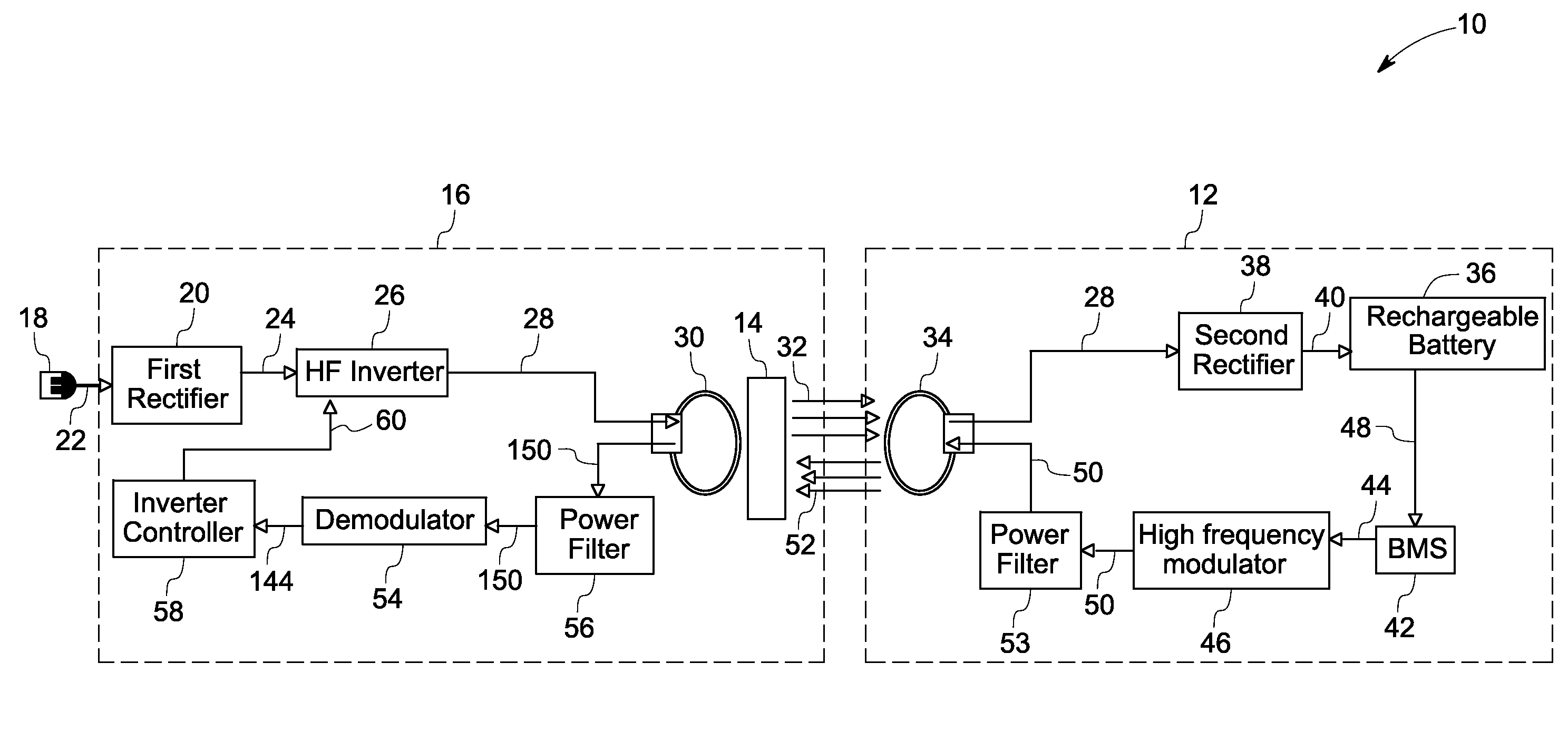
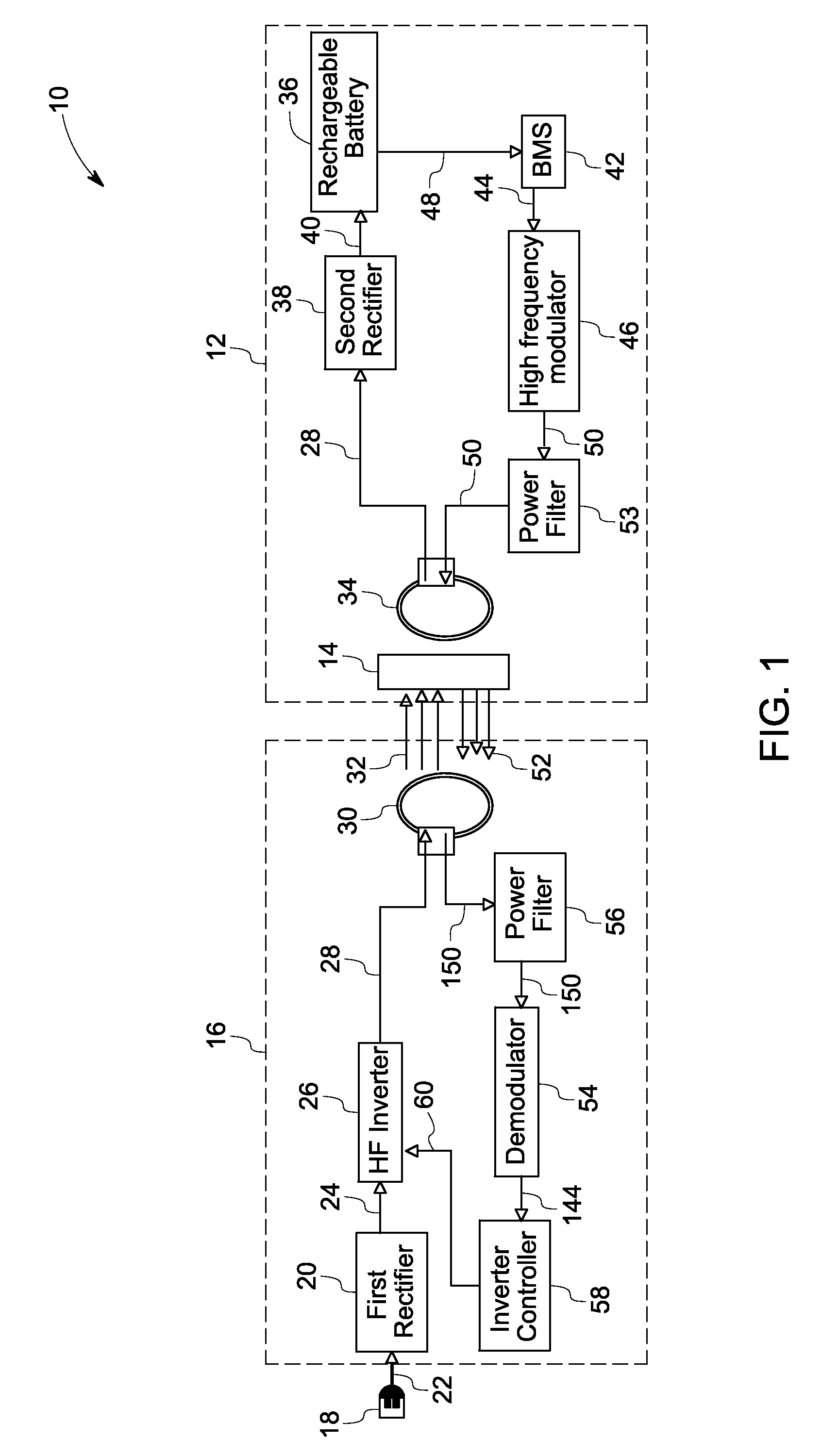
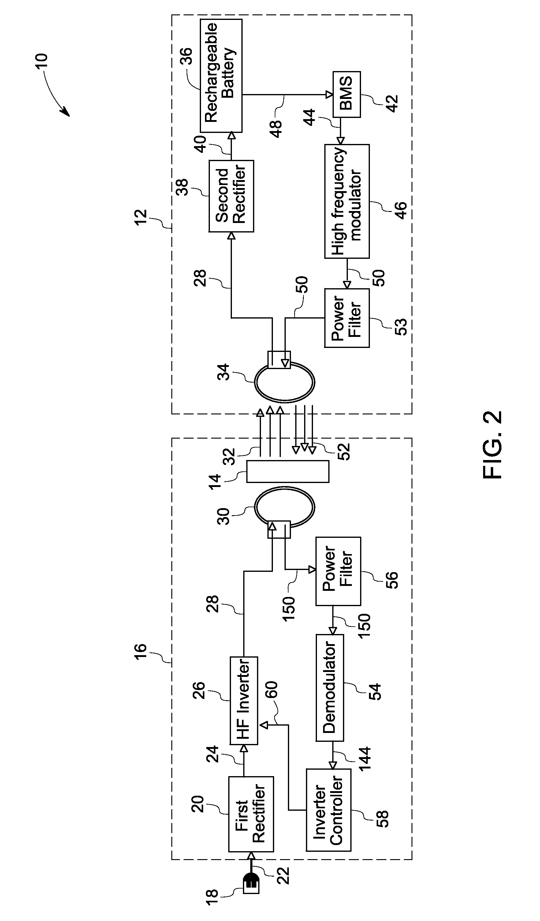
[0015]Embodiments of the present invention include a system for contactless power transfer in an implantable device for charging a rechargeable battery disposed within the implantable device. The system includes a first coil electrically couplable to a power source. The first coil produces a magnetic field that is coupled to a second coil electrically coupled to the rechargeable battery disposed within the implantable device. The second coil receives the power from the first coil via the magnetic field and further transfers the power to the rechargeable battery. The contactless power transfer system also includes a field-focusing element that is disposed between the first coil and the second coil. The field-focusing element acts as a self-resonant coil having a standing wave current distribution to focus the magnetic field onto the second coil and enhances the coupling between the first coil and the second coil. As used herein, the terms “a” and “an” do not denote a limitation of qu...


PUM


Abstract

A system and method for contactless power transfer in implantable devices for charging rechargeable batteries disposed within the implantable devices are provided. The system includes a first coil electrically couplable to a power source, wherein the first coil is configured to produce a magnetic field. The system further includes a second coil electrically coupled to the rechargeable battery disposed within the implantable device and configured to receive power from the first coil via the magnetic field and to transfer the power to the rechargeable battery. The system also includes a field focusing element disposed between the first coil and the second coil and configured as a self resonant coil having a standing wave current distribution to focus the magnetic field onto the second coil and enhance the coupling between the first coil and the second coil.

Description

BACKGROUND[0001]Embodiments of the present invention relate generally to contactless power transfer systems and more particularly to systems for contactless power transfer in implantable devices.[0002]Devices may be implanted in a human body for improving the operation of the human body and increasing life expectancy. The devices that may be implanted in the human body are known as implantable devices. Implantable devices operate on batteries, which may comprise non-rechargeable or rechargeable batteries.[0003]Non-rechargeable batteries typically are replaced after a fixed period of time. Battery replacement surgeries are expensive, complex, and inconvenient to the patient.[0004]However, use of rechargeable batteries are useful for extending the time between battery replacement surgeries. Conventionally, rechargeable batteries are recharged by an inductive coupling system. The inductive coupling system includes a primary coil and a capacitor placed outside the human body and a secon...

Claims


Application Information

Patent Timeline
Patent Type & Authority Applications(United States)
IPC IPC(8): A61N1/36A61N1/362A61F11/04
CPCA61N1/3787H02J5/005H04B5/0093H04B5/0037H02J7/025H02J7/00034H02J50/80H02J50/12H02J2310/23G09B23/28
Inventor BOHORI, ADNAN KUTUBUDDINRAMACHANDRAPANICKER, SOMAKUMARBHAT, SUMA MEMANA NARAYANA
Owner GENERAL ELECTRIC CO
Why Eureka
Try Eureka