

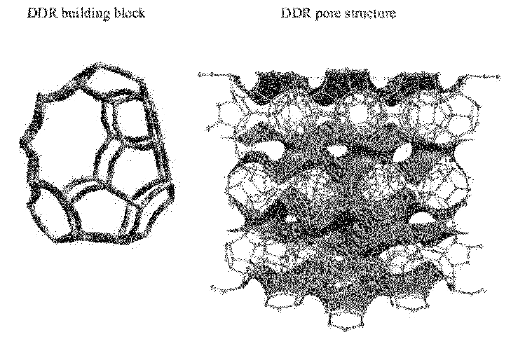
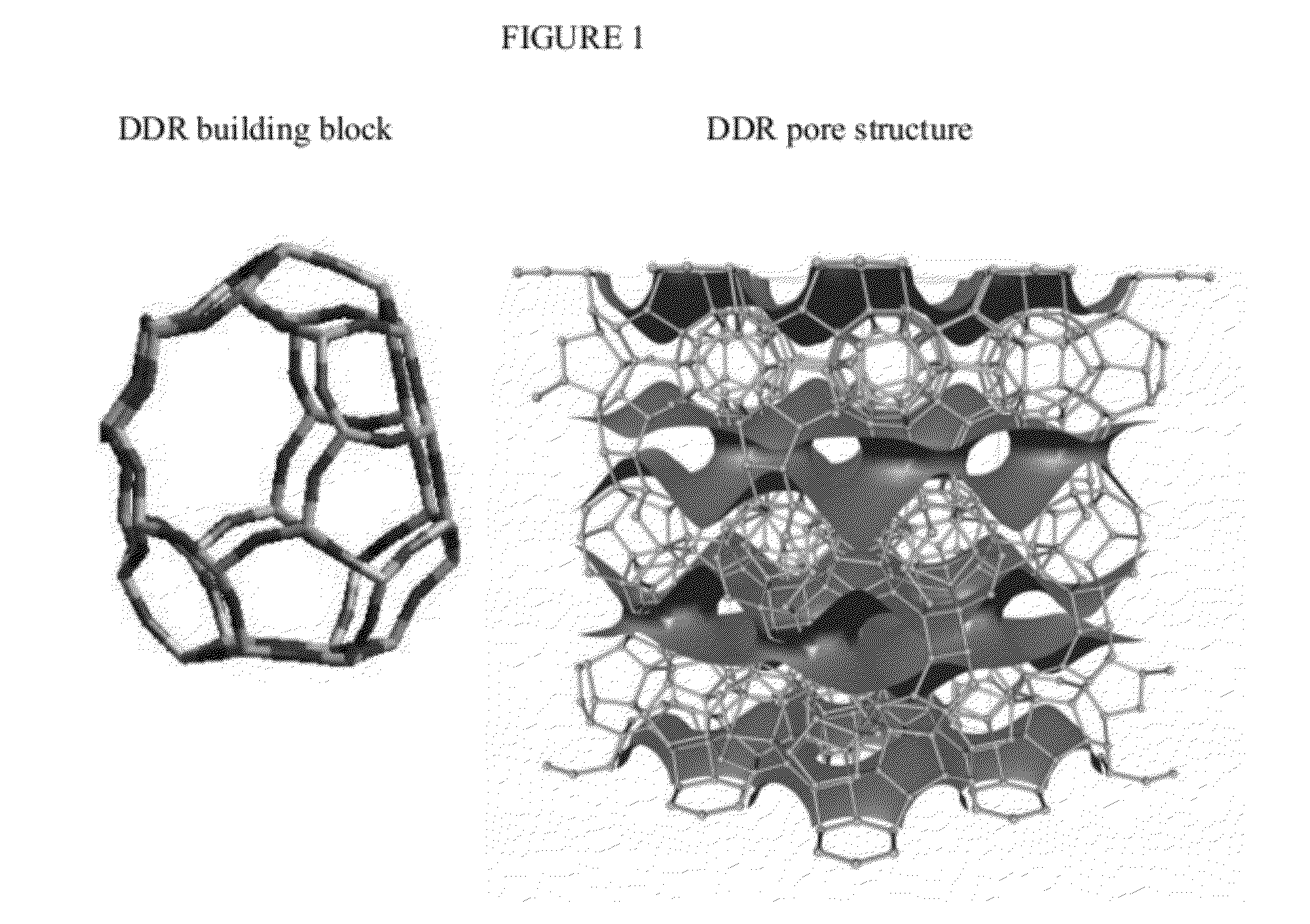
Zeolite DDR nanoparticles
- Summary
- Abstract
- Description
- Claims
- Application Information
AI Technical Summary
Benefits of technology
Problems solved by technology
Method used
Image

Examples
example 1
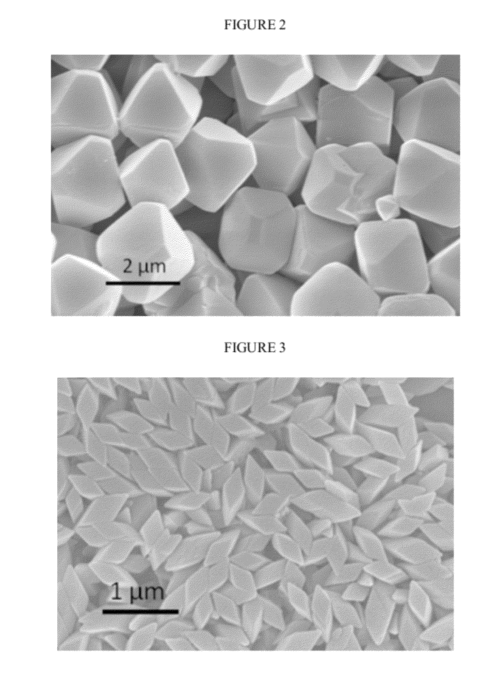
Octahedral DDR
[0039]Larger DDR crystals with octahedron morphology and approximate 2-micron size were synthesized in this first Example.
[0040]A mixture of ADA, Silica, KF and DI was made with the molar ratio of 6:100:50:8000. ADA was first dissolved in DI water. Due to the low solubility of ADA in water, the mixture was really only partially solubilized and much remained as a suspension of ADA in water. Silica was then added to the suspension and mixed. After mixing the suspension for 5-10 minutes, KF was added to the suspension. The mixture was further mixed at room temperature for 2 hours.
[0041]Next 30 grams of the mixture was poured into an autoclave with a Teflon liner of 45 ml. Then 5-10 grams of seed crystals were added to the autoclave. The autoclave was then sealed and heated to 160° C. inside an oven. The reaction was maintained for 48 hours. The autoclaves were then cooled to room temperature. The crystals were collected and washed with DI water and centrifuged for several...
example 2
Diamond DDR
[0043]In this Example, we show the synthesis of a DDR crystal with diamond-like morphology and approximate 500×250 nanometer size. General speaking, decreasing the time of the heat treatment unexpectedly changed the morphology and reduced the size.
[0044]In a typical synthesis, a mixture of ADA, Silica, KF and DI was made with the molar ratio of 6:100:50:10000. ADA was first dissolved in DI water. Due to the low solubility of ADA in water, the mixture was actually a partial suspension of ADA in water. Silica was then added to the suspension and mixed. After mixing the suspension for 5-10 minutes, KF was added to the suspension. The mixture was further mixed at room temperature for 2 hours.
[0045]After the mixture was prepared, 30 grams of the mixture was poured into an autoclave with a Teflon liner of 45 ml. 5 to 10 grams of seed crystals were added to the autoclave. The autoclave was then sealed and heated up to 160° C. inside an oven. The reaction was maintained for 8 hou...
example 3
Smaller Octhedral DDR
[0047]Next DDR crystals with octahedron morphology and approximately 300 nanometer size were synthesized. Generally, lowering the temperature and heating time reduced crystal size.
[0048]In a typical synthesis, a mixture of ADA, Silica, KF and DI was made with the molar ratio of 6:100:50:10000. ADA was first dissolved in DI water. Due to the low solubility of ADA in water, the resulting mixture was a suspension of ADA in water. Silica was then added to the suspension and mixed. After mixing the suspension for 5-10 minutes, KF was added to the suspension. The mixture was further mixed at room temperature for 2 hours.
[0049]After the mixture was prepared, 30 grams of the mixture was poured into an autoclave with a Teflon liner of 45 ml. 5 to 10 grams of seed crystals were added to the autoclave. The autoclave was then sealed and heated up inside an oven. To synthesize nanometer sized octahedral DDR nanocrystals, the temperature should be controlled less than or equa...
PUM
| Property | Measurement | Unit |
|---|---|---|
| Temperature | aaaaa | aaaaa |
| Temperature | aaaaa | aaaaa |
| Temperature | aaaaa | aaaaa |
Abstract
Description
Claims
Application Information