Density current baffle for a clarifier tank

a technology of density current and clarifier tank, which is applied in the direction of sedimentation settling tank, liquid displacement, separation process, etc., can solve the problems of affecting the settling of inaccurately defining the vertical location of the baffle on the wall of the clarifier, and difficulty in settling solids in the bottom of the clarifier tank. , to achieve the effect of increasing the flow rate of the clarifier tank and improving the performan

Active Publication Date: 2012-10-04
NEFCO SYST INC
View PDF3 Cites 7 Cited by
  • Summary
  • Abstract
  • Description
  • Claims
  • Application Information

AI Technical Summary

Benefits of technology

[0019]In one arrangement, the present baffle with a 30 degree inclination (downward from the horizontal or 60 degree upward from the vertical) combined with the extended horizontal projection above, advantageously provide an improving performance as flow rate within the clarifier tank increases.
[0020]Moreover, the location of the present baffle relative to the sludge blanket is arranged such that the distance from the top of the blanket to the lower, inboard (center) tip of the baffle, measured vertically, is substantially four feet. This arrangement provides the minimum space necessary for the baffle to intercept and deflect the density currents without creating a “short-circuit” to the launder flow.

Problems solved by technology

A major deterrent to effective removal is the presence of sludge density currents that cause hydraulic short circuits within the tank.
If the baffle projects too far into the tank it may adversely affect the settling of solids in the bottom of the clarifier tank (as desired in normal operations).
However, although these density current baffle systems work to significantly reduce solids from entering the effluent, under greater load conditions these baffle systems occasionally fan, allowing for the above described short circuits.
Accurately defining the vertical location of the baffle on the wall of the clarifier is difficult because the sludge blanket depth is not fixed and may vary over time.

Method used


Image

  • Density current baffle for a clarifier tank
  • Density current baffle for a clarifier tank
  • Density current baffle for a clarifier tank

Examples


Embodiment Construction

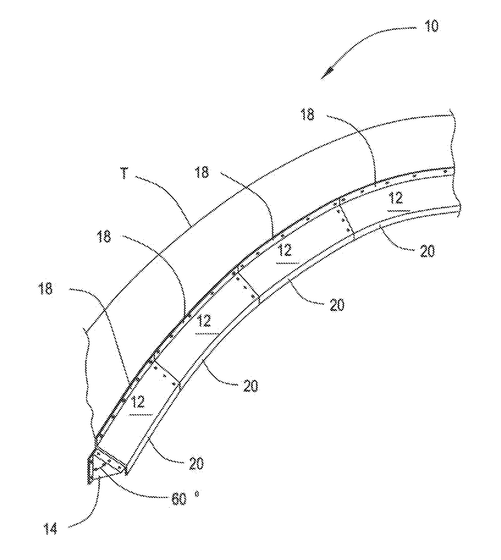
[0046]In one arrangement, as shown in FIG. 1, a density current baffle 10 is shown attached to a tank wall T. Density current baffle 10 is made from a plurality of connected baffle surfaces 12, each of which forming a portion of baffle 10 about the circumference of tank wall T.

[0047]Bracket elements 14 are positioned under baffle surfaces 12, preferably at the connection points between adjacent baffle surfaces as shown in FIG. 1. In one arrangement, an upper mounting flange 18 is located at the top edge of each of baffle surfaces 12 for coupling baffle surfaces 12 to tank wall T. Also as shown in FIG. 1, an end flange 20 projects downward from each of baffle surfaces 12, substantially perpendicular to tank wall T. Bracket element 14 and baffle surfaces 12 can be molded as a one piece fiberglass baffle.

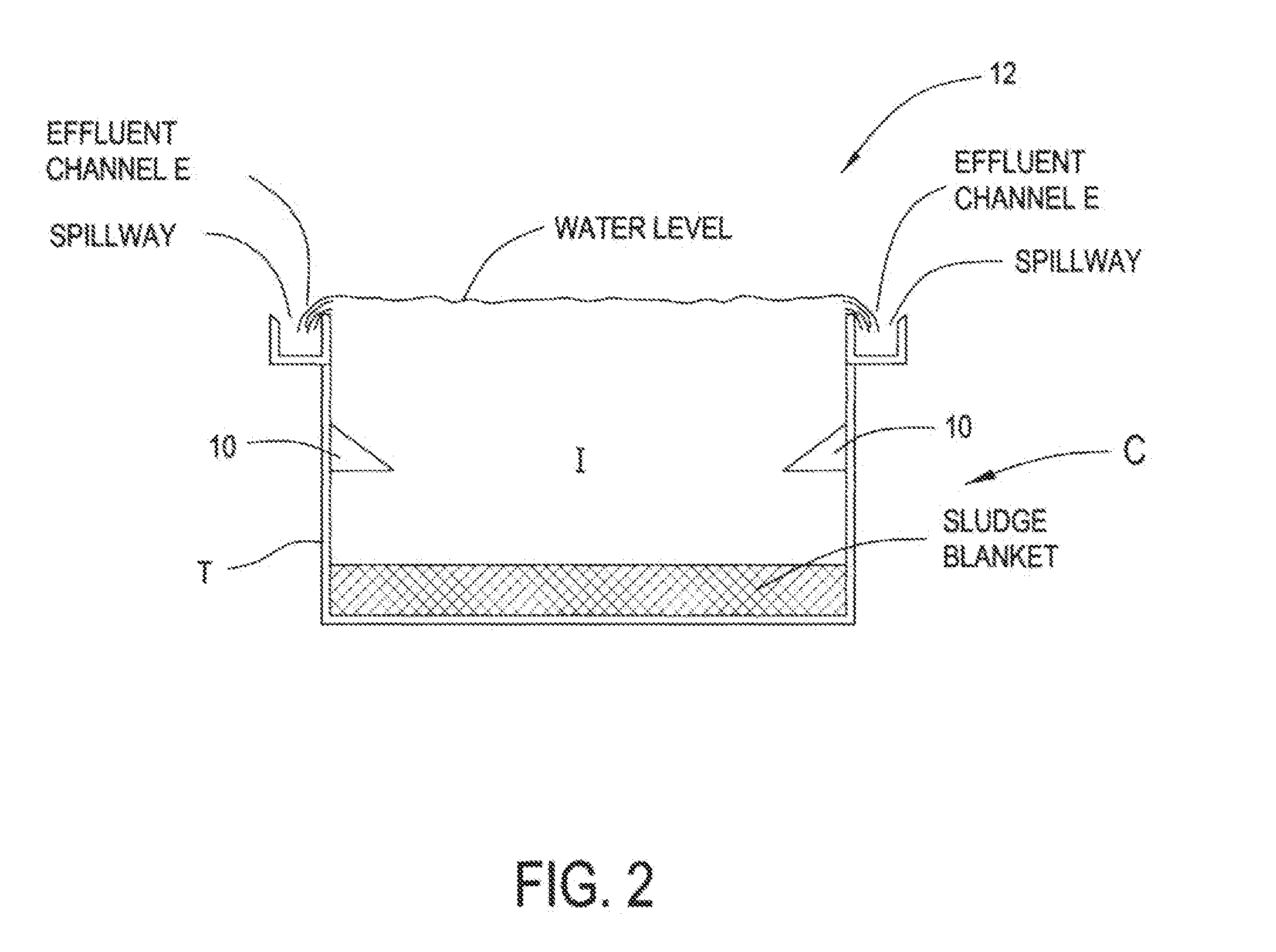
[0048]FIG. 2 shows a cut away view of baffle 10 within a typically circular type clarifier tank C, having an influent I, tank wall T, a spillway effluent channel and a weir W. Sludge b...


PUM

PropertyMeasurementUnit
diameteraaaaaaaaaa
diameteraaaaaaaaaa
angleaaaaaaaaaa

Abstract

In this respect, the present arrangement provides a density current baffle that employs a baffle that is dimensioned to balance the fact that larger horizontal projections of density current baffles improve performance while simultaneously recognizing that an overly large baffle would simply not correctly function, be unnecessarily large and complex and may in fact have a negative impact on the otherwise ordinary operation of flows within the clarifier tank. Thus, the present arrangement provides a baffle that improves performance while satisfying the desire to remain conservative in defining an upper limit for the projection. The horizontal projection of the baffle is structured according to the following equation:
HP=24″+0.4 inches/foot×(Diameter−30)

Description

RELATED APPLICATIONS[0001]This application claims the benefit of priority from U.S. Provisional Patent Application No. 61 / 441,007, field on Feb. 9, 2011, the entirety of which is incorporated by reference.FIELD OF THE INVENTION[0002]This application relates to a baffle and baffle system for use in a solids-precipitating clarifier tank. More particularly, the application relates to a baffle and baffle system having a plurality of inte engaged individual baffles secured to the clarifier tank peripheral wall.PRIOR ART DISCUSSION[0003]Passive baffle devices, also known in the art as a lamella gravity separators or settlers, are used in clarifier tanks for aste treatment for gravitationally separating suspended solids from solids containing carrier liquid or fluid suspensions. The clarifier tanks, with which such baffles are typically used, are circular or polygonal in shape in which a centrally mounted radially extending arm is slowly moved or rotated about the tank at or proximate to t...

Claims


Application Information

Patent Timeline
Patent Type & Authority Applications(United States)
IPC IPC(8): B01D21/02
CPCB01D21/0087B01D21/0042B01D21/0039B01D21/0003
Inventor SCHALLER, EARLE
Owner NEFCO SYST INC
Why Eureka
Try Eureka