HONEYCOMB STRUCTURE, Si-SiC BASED COMPOSITE MATERIAL, METHOD FOR MANUFACTURING HONEYCOMB STRUCTURE, AND METHOD FOR MANUFACTURING Si-SiC BASED COMPOSITE MATERIAL

a technology of honeycomb and composite material, which is applied in the direction of ceramics, physical/chemical process catalysts, and separation processes, etc., can solve the problems of insufficient electrical resistance between the electrode portion and the heat generation portion, and achieve the effect of reducing volume resistivity, forming more easily, and reducing volume resistivity

Inactive Publication Date: 2012-10-04
NGK INSULATORS LTD
View PDF13 Cites 16 Cited by
  • Summary
  • Abstract
  • Description
  • Claims
  • Application Information

AI Technical Summary

Benefits of technology

[0007]The present invention has been made in consideration of such problems, and regarding a Si—SiC based honeycomb structure, it is a main object to provide a honeycomb structure, a Si—SiC based composite material, a method for manufacturing a honeycomb structure, and a method for manufacturing a Si—SiC based composite material, wherein electrode portions are formed more easily and the volume resistivity can be further decreased.
[0022]In the present invention, regarding a Si—SiC based honeycomb structure, electrode portions are formed more easily, and the volume resistivity can be further decreased. The reason for this is not certain, but it is estimated as described below. For example, it is believed that regarding an impregnation base material in which metal Al is added to metal Si, the eutectic point of the impregnation base material is lowered and, in addition, Si oxides on the SiC phase surface and the impregnation base material surface can be reduced as compared with those in the case where metal Al is not added, so as to improve the wettability between the SiC particle surface and the impregnation base material. Meanwhile, it is believed that regarding the impregnation base material in which an alkaline-earth metal compound is further added, Si oxides on the SiC phase surface and the impregnation base material surface are removed by, for example, lowering the eutectic point of the oxide phase and facilitating movement in melt-impregnation, so as to ensure good wettability between the SiC particle surface and the impregnation base material. Then, it is estimated that even in the case where a large extent of oxide phase is present in the base material, the impregnation base material containing metal Si can be impregnated at normal pressure by combining the two described above. Furthermore, it is estimated that metal Al is impregnated together with metal Si and, thereby, the volume resistivity of the electrode portion can be further decreased as compared with the case where only metal Si is impregnated.

Problems solved by technology

Furthermore, the difference in electrical resistance between the electrode portion and the heat generation portion may be insufficient by only impregnation of Si.

Method used


Image

  • HONEYCOMB STRUCTURE, Si-SiC BASED COMPOSITE MATERIAL, METHOD FOR MANUFACTURING HONEYCOMB STRUCTURE, AND METHOD FOR MANUFACTURING Si-SiC BASED COMPOSITE MATERIAL
  • HONEYCOMB STRUCTURE, Si-SiC BASED COMPOSITE MATERIAL, METHOD FOR MANUFACTURING HONEYCOMB STRUCTURE, AND METHOD FOR MANUFACTURING Si-SiC BASED COMPOSITE MATERIAL
  • HONEYCOMB STRUCTURE, Si-SiC BASED COMPOSITE MATERIAL, METHOD FOR MANUFACTURING HONEYCOMB STRUCTURE, AND METHOD FOR MANUFACTURING Si-SiC BASED COMPOSITE MATERIAL

Examples


first embodiment

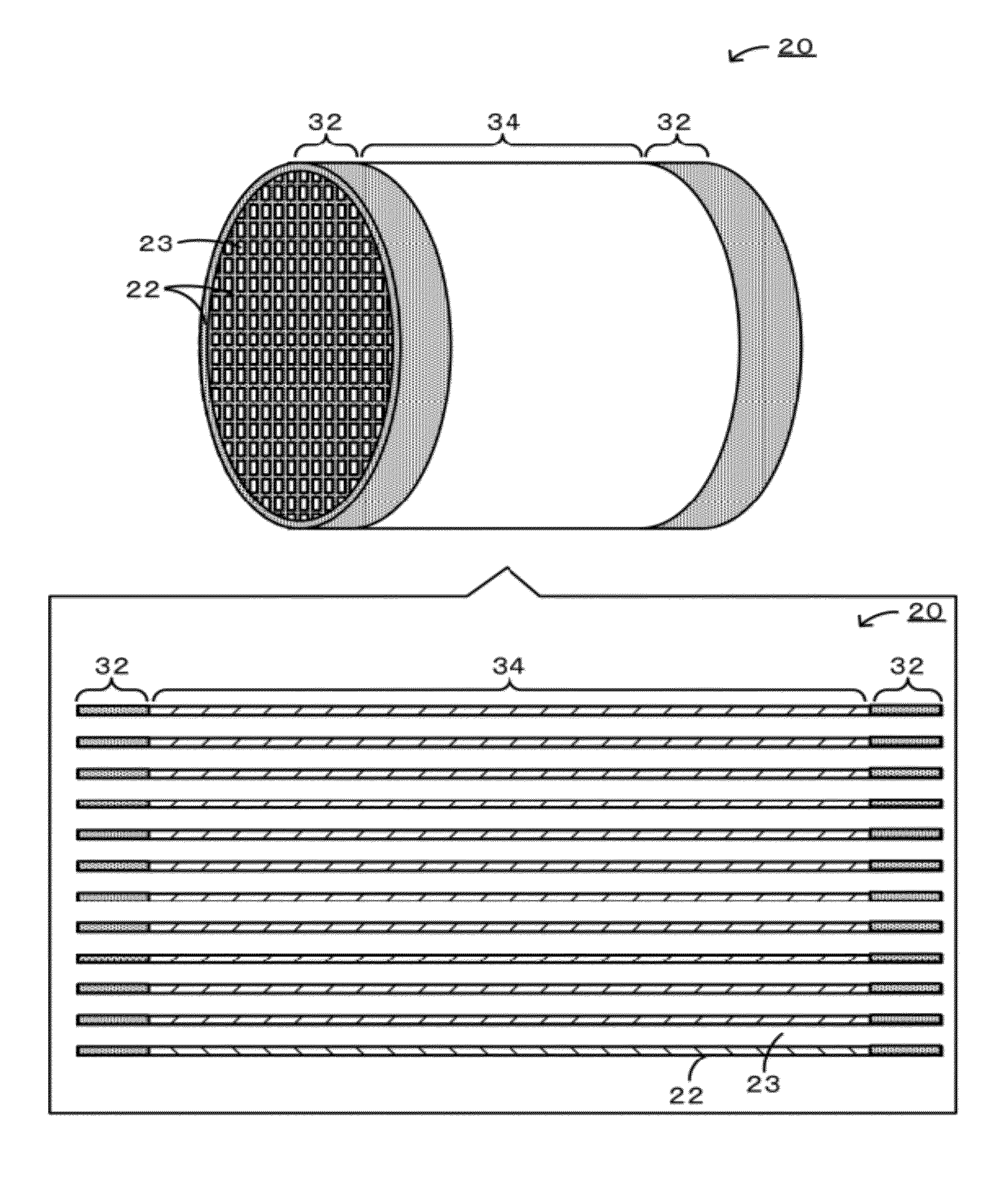
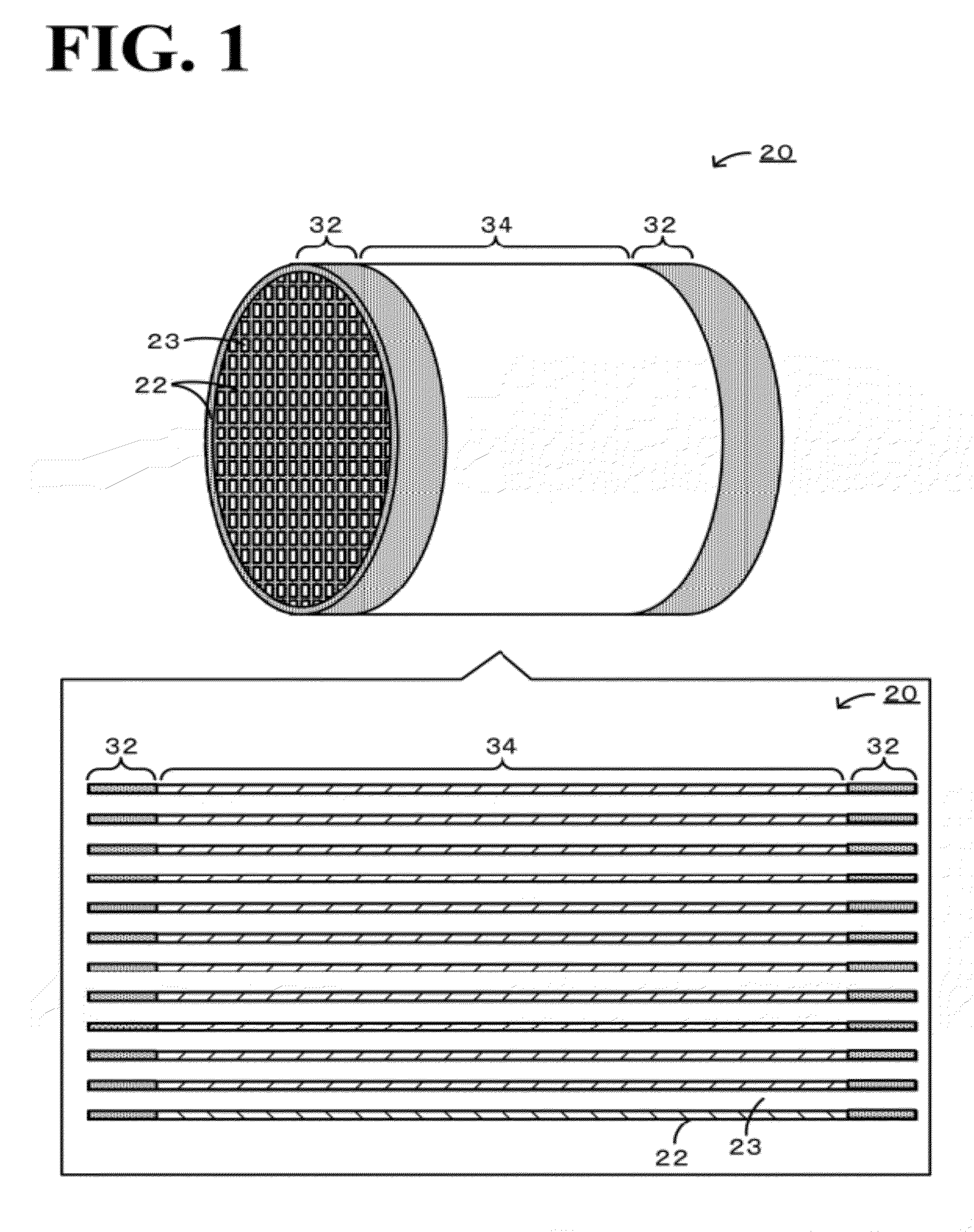
[0038]FIG. 1 is an explanatory diagram schematically showing an example of the configuration of a honeycomb structure 20 according to the present invention. As shown in FIG. 1, this honeycomb structure 20 is provided with a partition portion 22 constituting a plurality of cells 23 serving as flow paths of a fluid. This honeycomb structure 20 has a structure, in which both ends of the cell 23 are opened, and is provided with electrode portions 32 disposed as parts of the partition portion 22 and a heat generation portion 34 which is a part of the partition portion 22 and which has a volume resistivity higher than that of the electrode portion 32. Regarding this honeycomb structure 20, the partition portion 22 is formed and, thereafter, end portion regions thereof are subjected to a predetermined impregnation treatment, so as to convert parts of the partition portion 22 to electrode portions 32. Regarding this partition portion 22, the region not provided with the electrode portions 3...

second embodiment

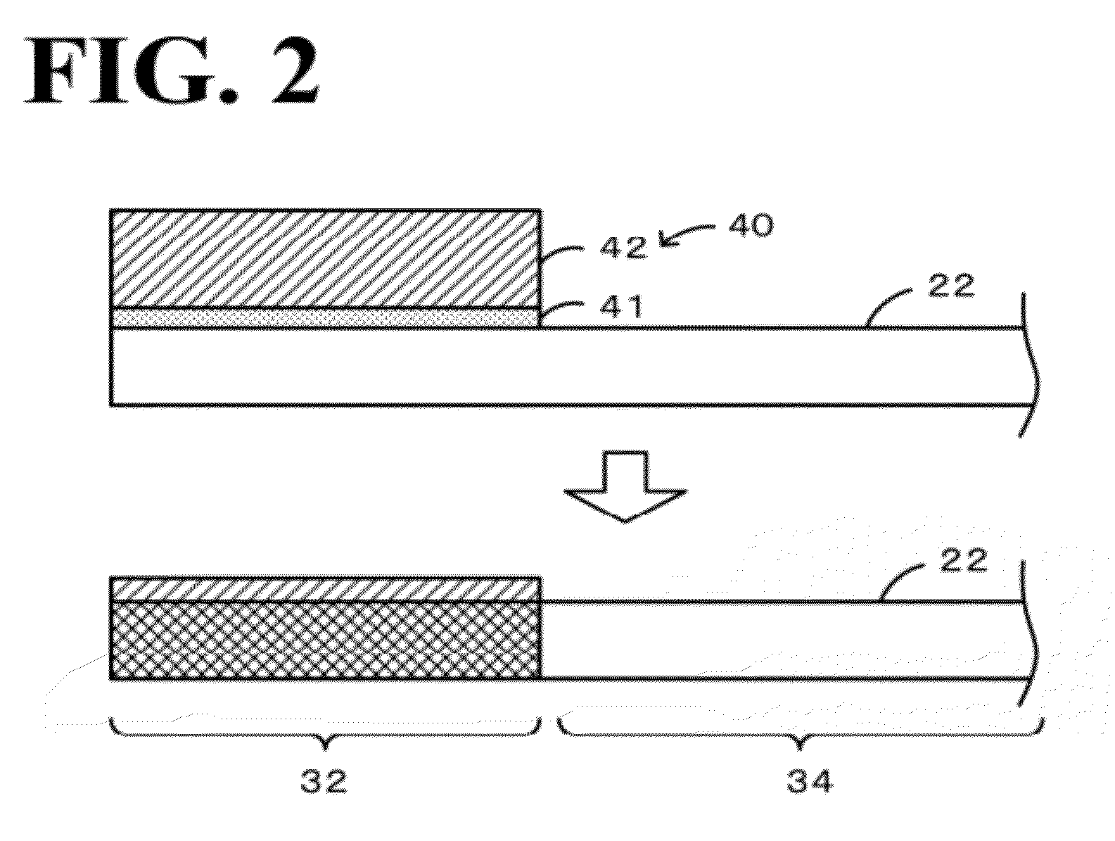
[0064]In the above-described first embodiment, the alkaline-earth metal compound and the impregnation base material are formed on the partition portion 22, and the partition portion 22 containing much oxide phase is subjected to a normal pressure impregnation treatment while the alkaline-earth metal compound is used as an impregnation auxiliary, so that the electrode portion 32 is formed as a part of the partition portion 22. In the present second embodiment, an aspect will be explained, in which after an oxide phase contained in a part of the partition portion serving as the electrode portion is removed in advance, the impregnation base material is formed on the partition portion, and the partition portion is subjected to the normal pressure impregnation treatment, so that the electrode portion is formed as a part of the partition portion. The honeycomb structure in this second embodiment is the same as the honeycomb structure in the first embodiment except that the alkaline-earth ...

examples

[0076]Concrete examples of production of honeycomb structures will be described below. Initially, an experiment with respect to the possibility of impregnation of an impregnation base material containing metal Si into a honeycomb base material having an oxide phase was performed. Here, a pellet base material was produced from the same material as that for the honeycomb base material. Impregnation material layers containing various impregnation base materials were formed on the resulting pellet base materials, a cross-section of each sample after execution of the impregnation step was observed, and thereby, whether the impregnation base material was impregnated into the honeycomb base material or not was examined.


PUM

PropertyMeasurementUnit
volume resistivityaaaaaaaaaa
temperatureaaaaaaaaaa

Abstract

A honeycomb structure is provided with a partition portion constituting a plurality of cells serving as flow paths of a fluid. This honeycomb structure includes electrode portions which are disposed as parts of the partition portion and which have a SiC phase, an oxide phase containing a Si oxide, an Al oxide, and an alkaline-earth metal oxide, and a metal phase containing metal Si and metal Al, where the proportion of metal Al relative to the total amount of metal Si and metal Al is 0.001 percent by mole or more and 20 percent by mole or less and a heat generation portion which is a part of the partition portion and which has a volume resistivity higher than that of the electrode portion.

Description

BACKGROUND OF THE INVENTION[0001]1. Field of the Invention[0002]The present invention relates to a honeycomb structure, a Si—SiC based composite material, a method for manufacturing a honeycomb structure, and a method for manufacturing a Si—SiC based composite material.[0003]2. Description of the Related Art[0004]Hitherto, as for honeycomb structures, the structures carrying catalysts to remove hazardous substances, e.g., nitrogen oxides, carbon monoxide, and hydrocarbons, contained in exhaust gases have been known. Regarding such structures, in the case where the temperature of an exhaust gas is low, hazardous substances may not be removed sufficiently. Then, a structure has been proposed, wherein the performance of exhaust gas cleaning is enhanced by heating a honeycomb structure, so as to raise the temperature of the exhaust gas passing through the honeycomb structure. For example, Patent literature 1 proposes a honeycomb body for energization heat generation, wherein heat genera...

Claims


Application Information

Patent Timeline
Patent Type & Authority Applications(United States)
IPC IPC(8): H05B3/02B05D5/12
CPCC04B35/565C04B2235/96C04B2235/3826C04B2235/428B01D46/0001B01D46/2425B01J35/04C04B41/85C04B41/009C04B41/5096C04B2111/0081B01D46/2429B01D46/2448C04B35/573C04B2235/5445C04B2235/5436C04B2235/442C04B2235/402C04B2235/3208C04B2235/80C04B35/6316C04B41/4539C04B41/4572C04B41/5155C04B2103/001C04B38/0006B01D46/24495
Inventor FURUKAWA, MASAHIROSHINSHI, MARIKOMATSUDA, KAZUYUKI
Owner NGK INSULATORS LTD
Why Eureka
Try Eureka