Method of dynamically compensating for magnetic field heterogeneity in magnetic resonance imaging

a magnetic resonance imaging and magnetic field heterogeneity technology, applied in the field of dynamic compensation for magnetic field heterogeneity in magnetic resonance imaging, can solve the problems of inability to improve image quality, adverse effects on the whole image quality, data inconsistency evolution, etc., to minimize the homogeneity, minimize the homogeneity, and reduce the workload of shim hardware performance

Inactive Publication Date: 2012-10-04
UNIVERSITATSKLINIKUM FREIBURG
View PDF3 Cites 54 Cited by
  • Summary
  • Abstract
  • Description
  • Claims
  • Application Information

AI Technical Summary

Benefits of technology

[0032]Another preferred embodiment or variant is a method where each sub-volume defined for the determination of the dynamically updated shimming parameters is chosen as the localized sub-volume which predominately contributes signal to the acquired data of a shot, or a set of shots, of a multi-shot imaging sequence, where a shot is defined as the time between the beginning of each excitation RF pulse train and the end of the corresponding data recording. The advantage of this embodiment is that shimming parameters need to be updated only once or less per shot, making the sequence less demanding for shim hardware performance. The term “predominately” refers to the fact that the spatial frequency energy of the object is not focused exactly at zero frequency. However, most of the energy of the signal is concentrated at very low spatial frequencies. This issue and related effects have been analyzed in detail in {40} and therefore the term “predominately” must be interpreted in view of the publication {40}.
[0033]Another preferred embodiment or variant is a method where each sub-volume defined for the determination of the dynamically updated shimming parameters is chosen as the localized sub-volume which predominately contributes signal to a subset of the acquired data of a single-shot imaging sequence or to a subset of acqu...

Problems solved by technology

However, this method does not allow one to improve the image quality by updating the shimming parameters during the acquisition of a single slice.
First, the image quality might b...

Method used


Image

  • Method of dynamically compensating for magnetic field heterogeneity in magnetic resonance imaging
  • Method of dynamically compensating for magnetic field heterogeneity in magnetic resonance imaging
  • Method of dynamically compensating for magnetic field heterogeneity in magnetic resonance imaging

Examples


Embodiment Construction

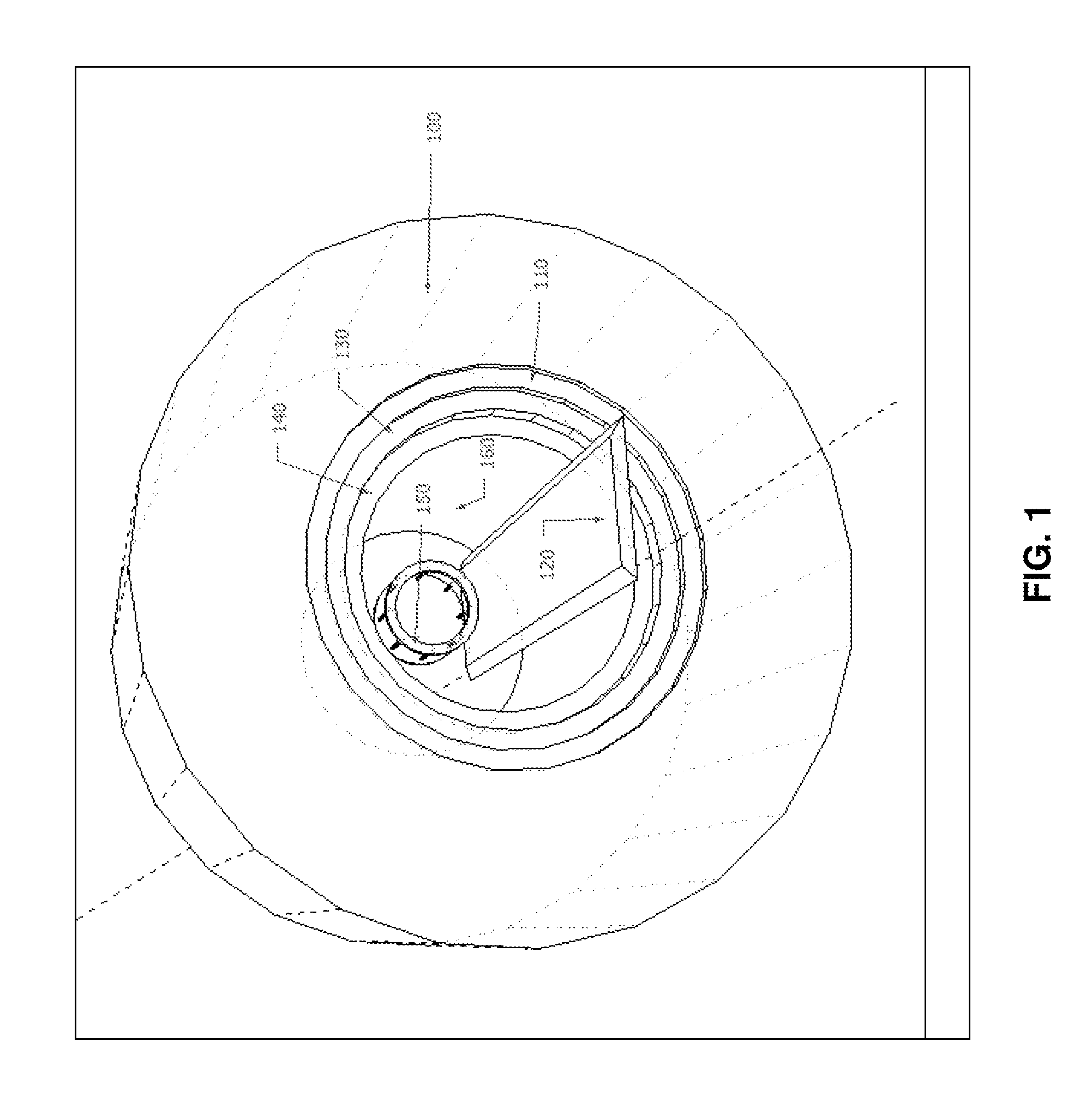
[0046]FIG. 1 is an illustration of a main magnet 100 of a nuclear magnetic resonance device with an axial 170 room temperature bore 160. The arrangement of the bore 160 is such that the operating component of static magnetic field encompasses the radiofrequency coil 150, which is used to deliver radiofrequency pulses to excite a transverse magnetization within an object of investigation, e.g. a human subject, who lies on the bed 120. The bed 120 is suspended near center of the concentric part of the bore 160, such that the object of investigation lies directly in the radiofrequency coil 150. The illustration of the RF coil 150 is a ‘birdcage’ style coil, although it is well known that other geometries, sizes or a plurality of RF coils may be used to generate a transverse magnetization. There are many common configurations of nuclear magnetic resonance devices, e.g. the bore 160 may lie in a vertical direction. The main magnet 100 may consist of resistive conducting elements or super...


PUM


Abstract

A method to compensate for the magnetic field heterogeneity inside an object of investigation in a MR device obtains an uncorrected magnetic field distribution of the object and executes an MR sequence with a desired k-space coverage by applying RF pulses to generate a transverse magnetization within the object. MR signal data is recorded, magnetic field shimming parameters are dynamically updated and MR signal data are reconstructed to produce images or localized spectroscopic data. Artifacts in a reconstructed image resulting from an uncorrected magnetic field distribution are suppressed by temporally separating MR signals originating from at least two different sub-volumes within a volume of transverse magnetization by generating a nonlinear phase distribution within the object and by dynamically updating shimming parameters to compensate for the field inhomogeneity distributions within the different sub-volumes in the volume of transverse magnetization.

Description

[0001]This application claims Paris Convention priority of EP 11 160 229.8 filed Mar. 29, 2011 the complete disclosure of which is hereby incorporated by reference.BACKGROUND OF THE INVENTION[0002]This invention relates to a method to compensate for the magnetic field heterogeneity inside of an object of investigation inside of a magnetic resonance device, comprising:(A) determining experimentally or theoretically spatial field distributions and temporal switching characteristics of field manipulating coils present in the magnetic resonance (MR) apparatus including B0 offset coil, linear gradients, non-linear encoding fields and shim coils of first and higher orders;(B) obtaining an uncorrected magnetic field distribution of the object of investigation by measuring (i) the heterogeneity of the static magnetic field and (ii) the heterogeneity caused by susceptibility variations associated with the object of investigation;(C) executing an MR sequence on the MR device with a desired k-...

Claims


Application Information

Patent Timeline
IPC IPC(8): G01R33/58
CPCG01R33/3875
Inventor WITSCHEY, WALTERZAITSEV, MAXIMHENNIG, JURGENSCHULTZ, GERRITGALLICHAN, DANIEL
Owner UNIVERSITATSKLINIKUM FREIBURG
Why Eureka
Try Eureka