Laser processing method

a laser processing and cutting surface technology, applied in the field of laser processing methods, can solve the problems of inability to increase the length of the modified area in the thickness direction of the material to be processed too much, and the variation of the shape of the cut surface, so as to achieve the effect of suppressing the increase in cost and excellent cutting surface shap

Active Publication Date: 2012-10-11
SUMITOMO ELECTRIC IND LTD +1
View PDF3 Cites 106 Cited by
  • Summary
  • Abstract
  • Description
  • Claims
  • Application Information

AI Technical Summary

Benefits of technology

[0008]The present invention has been made to solve the above problems and an object of the present invention is to provide a laser processing method by which an excellent shape of a cut surface can be achieved and an increase in cost can be suppressed.
[0010]With such a configuration, since the wavelength components forming the continuous spectrum are focused and thereby the focusing line (collection of the focusing points) is formed, the modified area extending long in the irradiation direction of the laser beam (e.g., in the depth direction) can be formed in an area where the focusing line is located or on the axis of the focusing line in the material to be processed. Therefore, when the material to be processed is cut using the modified area as an origination area, the shape of a cut surface can be flattened in a stable manner because the modified area extending long in the certain direction preexists. In addition, since the modified area extending long in the irradiation direction of the laser beam can be formed by one laser irradiation, the process cost can be reduced as compared with the case where laser irradiation is repeated a plurality of times.
[0013]With such a configuration, the pulsed laser of the predetermined spectral band is focused as the laser beam, and thereby the focusing portion of each spectral component included in the pulsed laser is formed on the straight line in the focusing direction or linearly along the focusing direction as the focusing area. Therefore, the modified area generated from the focusing area extending linearly can be formed inside the material to be processed. Thus, when the material to be processed is cut using the modified area as an origination area, the shape of a cut surface can be flattened in a stable manner because the modified area extending long in the certain direction preexists. In addition, since the modified area extending in the focusing direction of the laser beam can be formed by one laser irradiation, the process cost can be reduced as compared with the case where laser irradiation is repeated a plurality of times.
[0014]According to the present invention, there can be realized a laser processing method by which an excellent shape of a cut surface can be achieved and an increase in cost can be suppressed.

Problems solved by technology

The aforementioned conventional laser processing methods, however, have had the following problems.
Therefore, the length of the modified area in the thickness direction of the material to be processed cannot be increased too much.
As a result, the direction and the like of a crack developing from the modified area in cutting processing are not fixed in some cases, which may result in variations in the shape of a cut surface.
In the laser processing method disclosed in PTL 2, although the plurality of modified areas can be formed in the depth direction of the material to be processed, laser beam irradiation must be performed a plurality of times to form the plurality of modified areas, which causes a problem of an increase in the number of steps in the manufacturing process and thus an increase in the manufacturing cost.
In the laser processing method disclosed in PTL 3, although the laser beam having an extremely-short pulse width in the femtosecond range is used, the industrial use of such laser beam having an extremely-short pulse width is not practical in terms of the apparatus cost, the stability of the process and the like.
As described above, it has been conventionally difficult to cut the material to be processed by laser processing in a short time and at low cost, and to achieve the excellent shape of the cut surface.

Method used


Image

  • Laser processing method
  • Laser processing method
  • Laser processing method

Examples


experiment 1

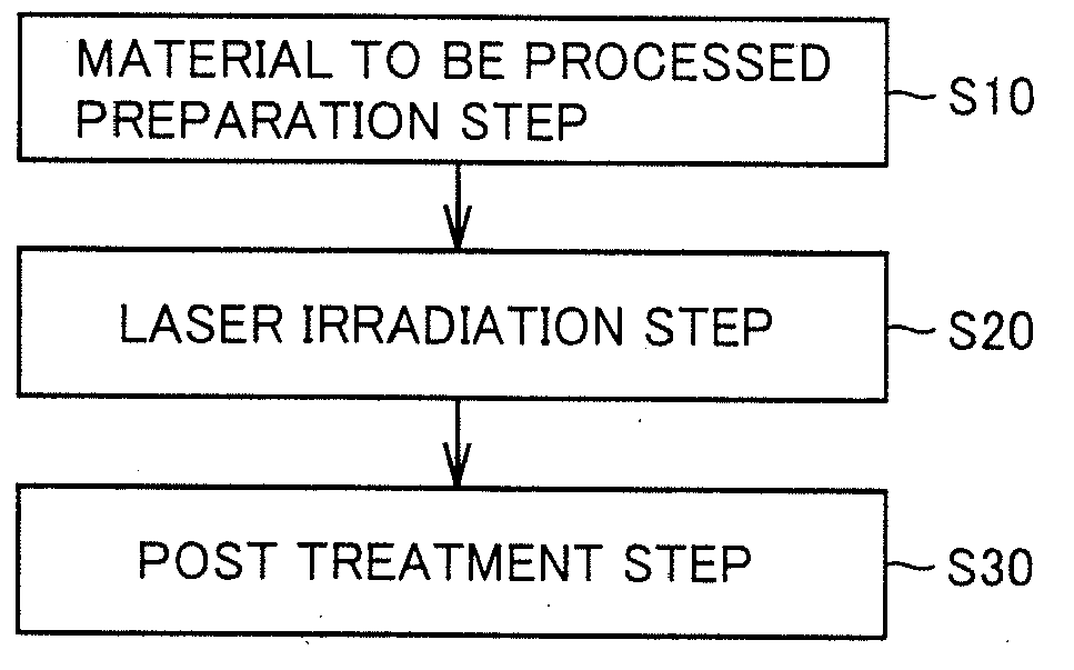
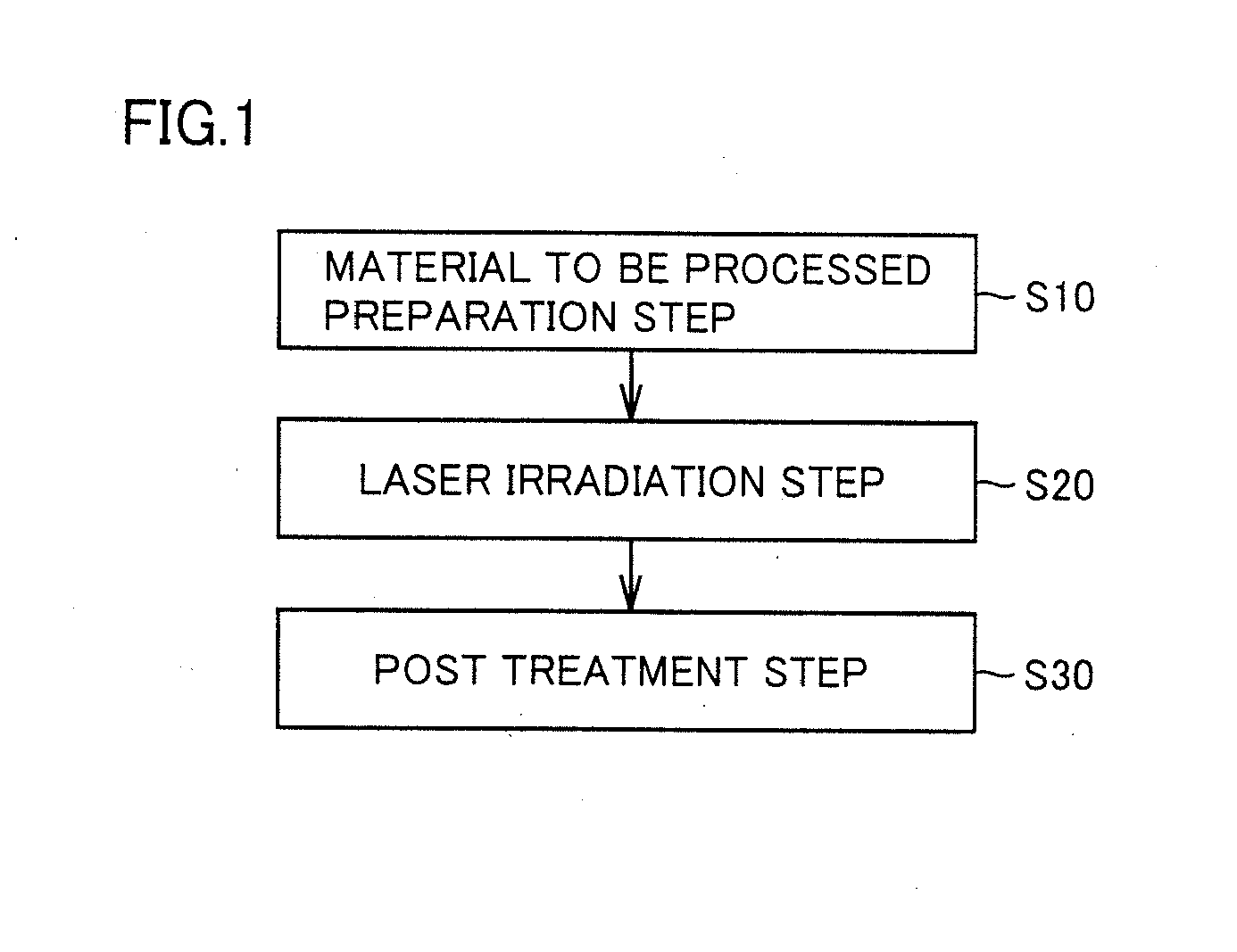
[0155]An experiment as described below was conducted to describe the effect of the laser processing method according to the present invention. In the following experiment, the pulse width of pulsed laser used as the laser light source was set to 180 ps.

[0156](Specimen)

[0157]A sapphire substrate having a thickness of 400 μm was prepared as a specimen of a material to be processed in the laser processing method according to the present invention. The sapphire substrate had a square planar shape of 10 mm long and 10 mm wide. The surface (glossy surface 12) of the specimen was mirror-finished and the lower surface (satin-finished surface 13) was satin-finished.

[0158](Contents of Experiment)

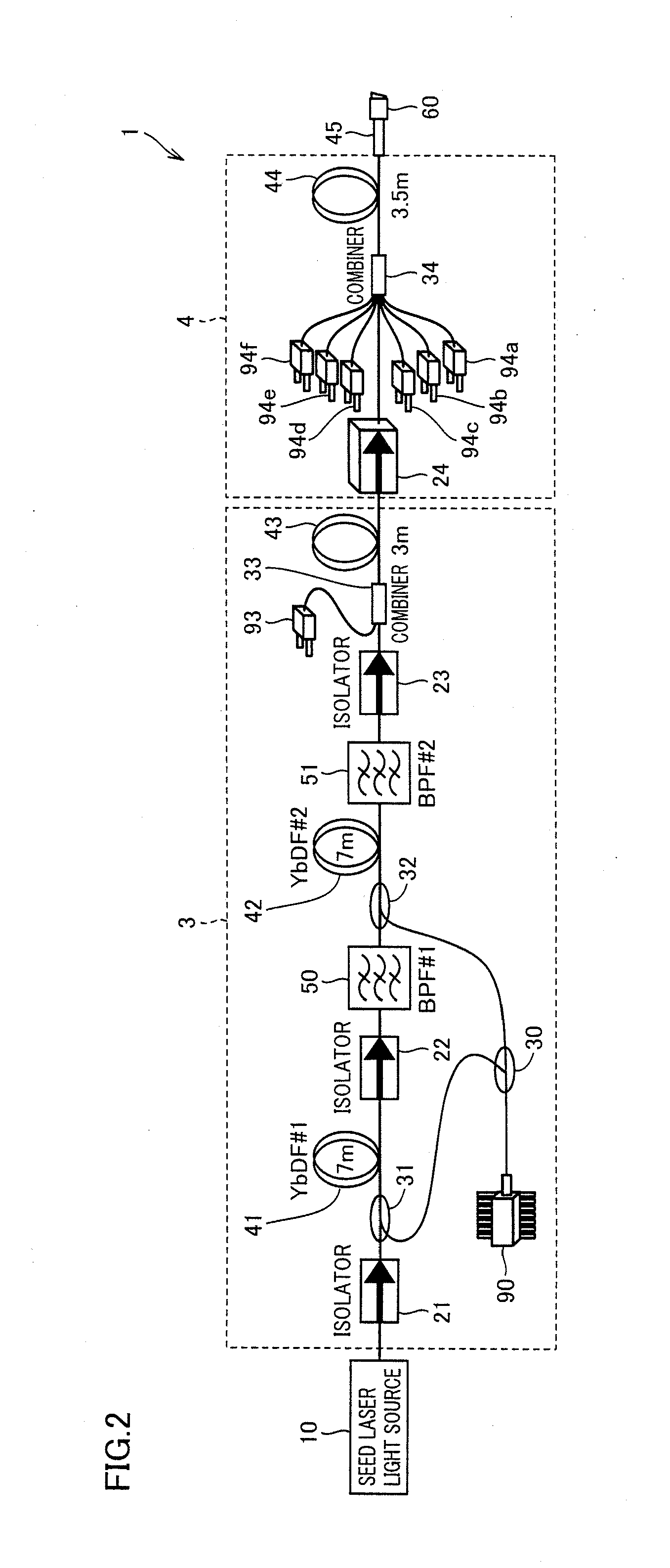
[0159]Pulsed laser beam obtained from the MOPA laser light source shown in FIG. 2 was focused using a lens having a focal length of 20 mm, and the sapphire substrate serving as the material to be processed was irradiated with the focused pulsed laser beam. The laser beam entering the lens had a beam d...

experiment 2

[0171]The laser beam irradiation conditions were changed and an experiment was conducted to check the effect of the laser processing method according to the present invention.

[0172](Specimen)

[0173]A specimen (sapphire substrate) similar to the specimen prepared in aforementioned Experiment 1 was prepared as a material to be processed.

[0174](Contents of Experiment)

[0175]Laser processing of the prepared sapphire substrate was performed similarly to Experiment 1. The laser beam irradiation conditions were basically similar to those in aforementioned Experiment 1 except that the moving speed of the specimen was set to 40 mm / s. Using conditions similar to conditions 1 to 4 in aforementioned Experiment 1 as conditions about the distance between the specimen and the lens, laser processing experiments were conducted, respectively. Then, a side surface of a laser beam-irradiated area and a laser-irradiated surface (glossy surface) of the processed specimen were observed with the optical micr...


PUM

PropertyMeasurementUnit
peak wavelengthaaaaaaaaaa
spectral widthaaaaaaaaaa
surface roughnessaaaaaaaaaa

Abstract

There is obtained a laser processing method by which an excellent shape of a cut surface can be achieved and an increase in cost can be suppressed. A laser processing method includes the steps of: preparing a material to be processed; and forming a modified area in the material to be processed, by irradiating the material to be processed with laser beam. In the aforementioned step, pulsed laser beam having a continuous spectrum is focused with a lens, thereby forming a focusing line constituted by a plurality of focuses that are obtained by predetermined bands forming the continuous spectrum of the laser beam, and the material to be processed is irradiated with the laser beam such that at least a part of the focusing line is located on a surface of the material to be processed, thereby forming the modified area on an axis of the focusing line.

Description

BACKGROUND OF THE INVENTION[0001]1. Field of the Invention[0002]The present invention relates to a laser processing method, and more particularly to a laser processing method used for cutting and cleaving or division processing of a material to be processed.[0003]2. Description of the Background Art[0004]A laser processing method using laser beam to cut and cleave a material to be processed has been conventionally known (see, for example, Japanese Patent Laying-Open No. 2002-192370 (hereinafter referred to as PTL 1), Japanese Patent Laying-Open No. 2002-205180 (hereinafter referred to as PTL 2) and Japanese Patent Laying-Open No. 2008-6492 (hereinafter referred to as PTL 3)).[0005]PTL 1 discloses that a wafer-like material to be processed is irradiated with laser beam having a pulse width of 1 μs or less such that a focusing point (focus) of the laser beam is arranged inside the material to be processed, thereby forming a modified area, which serves as a starting point of cutting pr...

Claims


Application Information

Patent Timeline
Patent Type & Authority Applications(United States)
IPC IPC(8): B23K26/00B28D5/00B23K26/38B23K26/53
CPCB23K26/0042B23K26/0063B23K26/0869B23K26/10H01L21/302B23K26/4075B23K26/36B23K26/365B23K26/367B23K26/38B23K26/0006B23K26/0617B23K26/40B23K26/53B23K26/57B23K26/361B23K26/364B23K2103/50B23K2103/56
Inventor KAKUI, MOTOKIKOHDA, HIROSHIKANEUCHI, YASUOMITAMAOKI, SHINOBUNAGANO, SHIGEHIROUNO, YOSHIYUKIOKAMOTO, YASUHIROTAKAHASHI, KENTA
Owner SUMITOMO ELECTRIC IND LTD
Why Eureka
Try Eureka