

Real time averaged impedance calibration for on-die termination
- Summary
- Abstract
- Description
- Claims
- Application Information
AI Technical Summary
Benefits of technology
Problems solved by technology
Method used
Image

Examples
Embodiment Construction
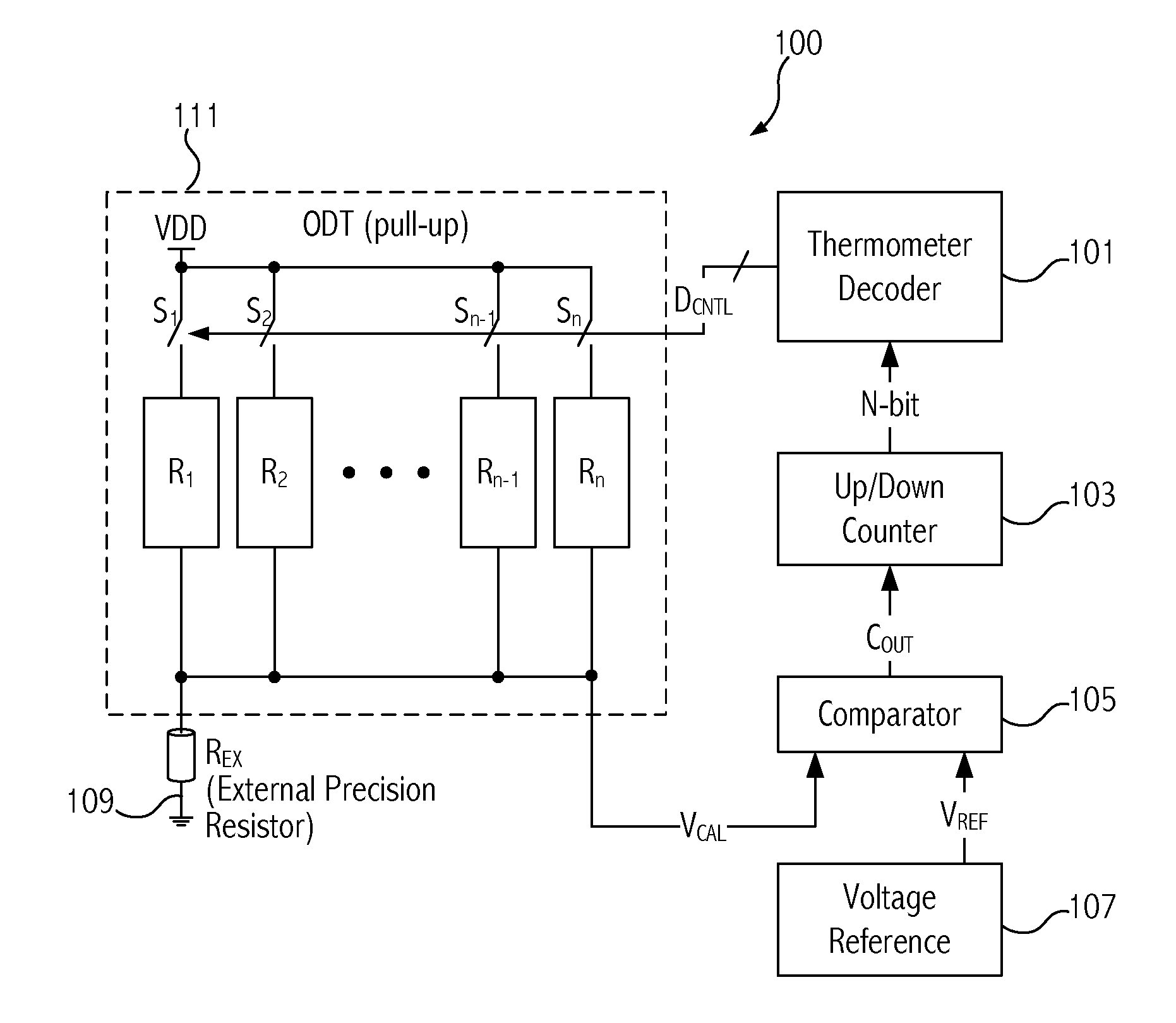
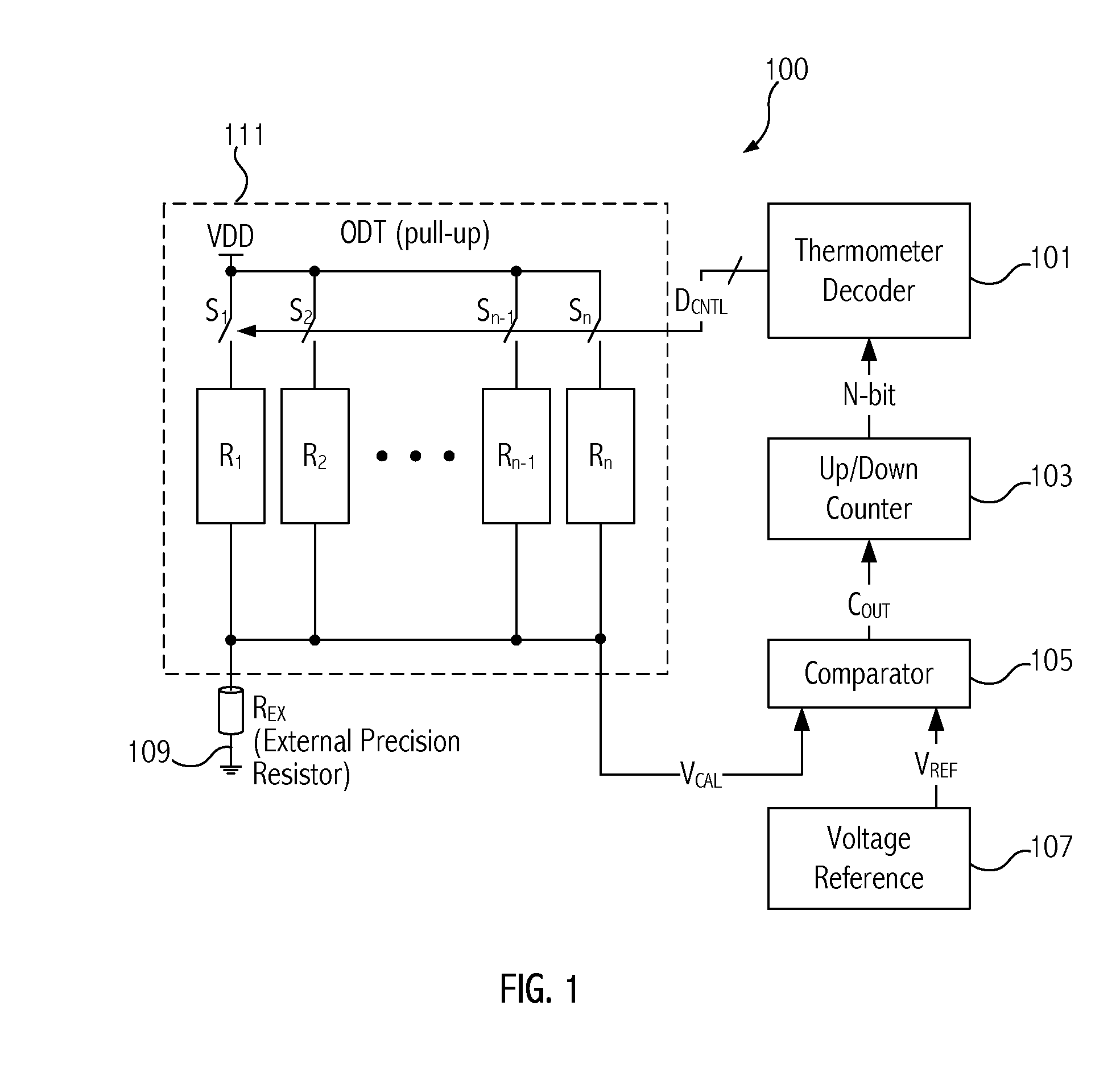
[0017]Improvements in on-die termination can lead to greater accuracy, smaller area utilized, and less toggling. Embodiments of the invention provide an impedance calibration technique for on-die termination (ODT) with better accuracy than prior approaches without increasing resolution by utilizing an averaging impedance technique.
[0018]In one embodiment, a method is provided for a calibrated termination impedance that includes supplying first and second control signals having different values to configure respectively first and second switch arrays and associated first and second resistive loads coupled in parallel. Each of the resistive loads has their respective resistance values determined by configuration of the switch arrays. The first control signals cause the first resistive load to have a first resistance value and the second control signals cause the second resistive load to have a second resistance value that differs from the first resistance value. In embodiments, the fi...
PUM
 Abstract
Description
Claims
Application Information