
Integrated magnetics with isolated drive circuit

Active Publication Date: 2012-10-11
BEL POWER SOLUTIONS INC
View PDF12 Cites 24 Cited by
  • Summary
  • Abstract
  • Description
  • Claims
  • Application Information

AI Technical Summary

Benefits of technology

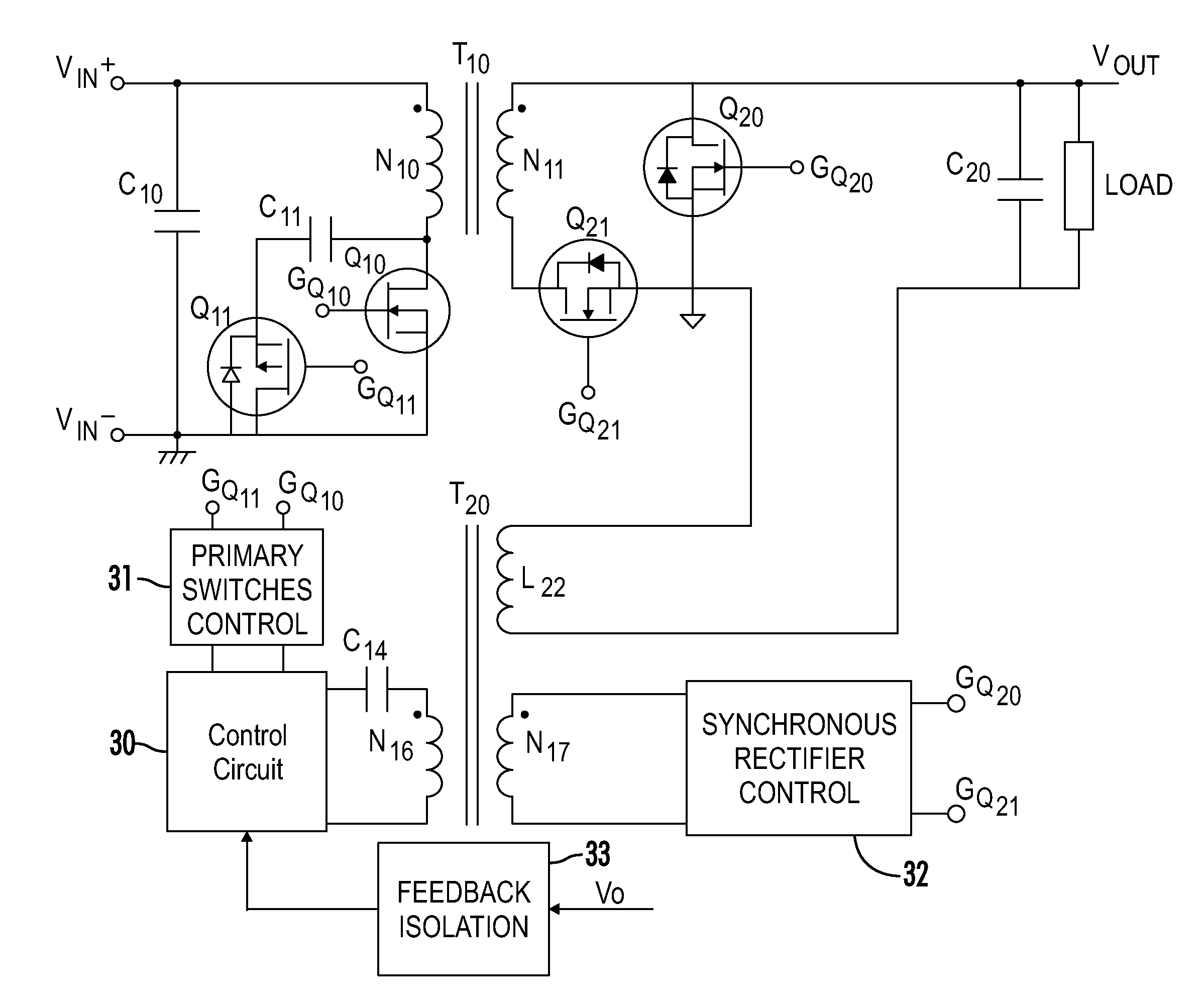
[0035]According to an embodiment of the invention, the windings of a drive transformer are embedded into a power transformer or inductor so that a separate magnetic core is not needed for the drive transformer. The windings of the drive transformer are wound around an outer leg of an E-shaped core, while windings of power transformer or inductor are wound around the center leg. Such a winding structure is used to keep the windings of the drive transformer tightly coupled, and at the same time, loosely coupled with the windings of the power transformer or inductor. Because of the loose coupling, it is possible to have different voltage waveforms in the windings of the drive transformer and windings of power transformer or inductor for a short period of time sufficient to initiate turn-on or turn-off of the controllable switches without significant voltage and current stresses in the circuitry for driving the drive transformer. The number of windings used in the drive transformer depends on the application as well as the converter topology. The maximum volt-second that the drive transformer can support is defined by the power transformer or inductor.
[0037]Another aspect of the invention is that the drive voltage may be clamped in order to be independent of changes in the input voltage. The clamped energy is used to power the control and drive circuitry after initial start-up of the converter thus simplifying the bias circuit and reducing power requirements during normal operation of the converter.

Problems solved by technology

This is primarily due to a lack of need for additional isolation between drive signals for the input side switches and the synchronous rectifiers.
However, simplicity has its drawbacks.
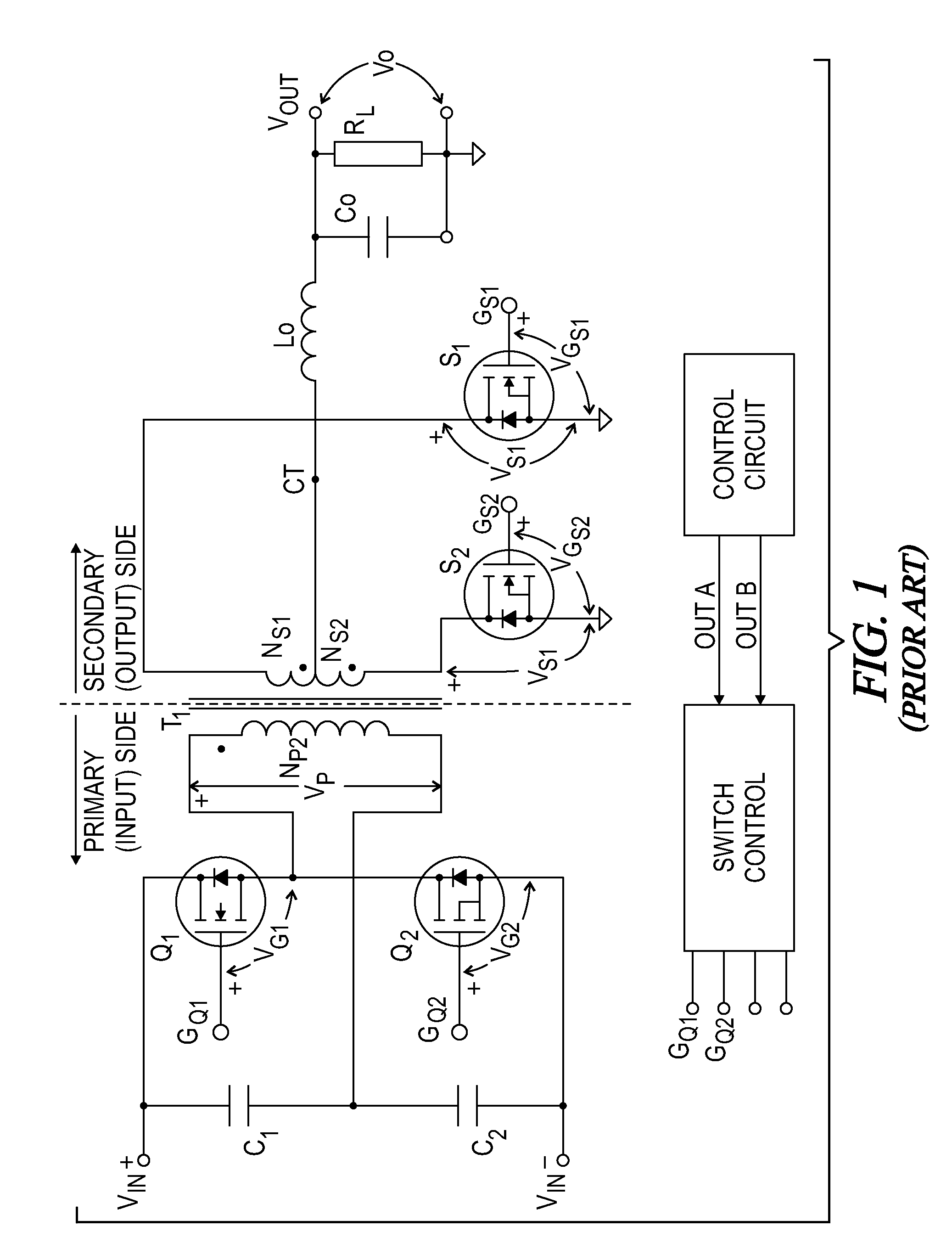
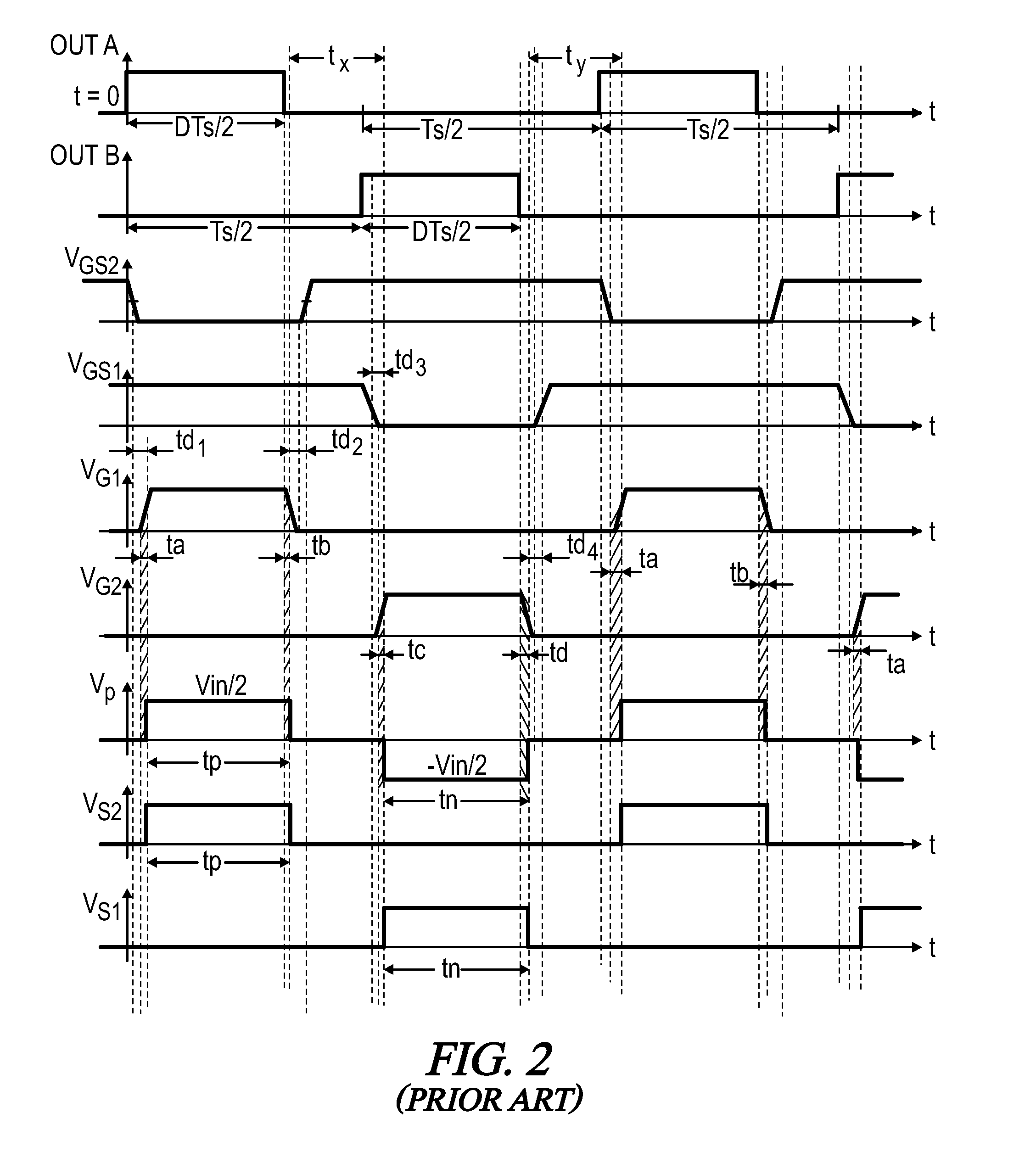
These drawbacks include: (a) cross conduction between the synchronous rectifiers and the primary side switches; (b) the drive voltage, being derived from a power transformer, varies with changes in input voltage and thus requires additional clamp circuitry and results in additional losses; and (c) the timing between the drive signals depends heavily on circuit parasitics.
A disadvantage of this solution is that the drive transformer only transfers the PWM signal from one side of the converter to the other side and requires additional switch control circuitry as well as a power source for the driving switches.
This has a negative effect on the overall efficiency of the converter.
In applications that require extremely high efficiency of the converter for a given size, operation at lower switching frequencies is needed which increases the size of the power transformer and output inductor.
This leaves no room on the circuit board for a separate drive transformer or any other solutions for isolating the drive signals between the input and output of the converter, such as fast opto-couplers or opto-isolators.

Method used


Image

  • Integrated magnetics with isolated drive circuit
  • Integrated magnetics with isolated drive circuit
  • Integrated magnetics with isolated drive circuit

Examples


Embodiment Construction

[0054]Throughout the specification and claims, the following terms take at least the meanings explicitly associated herein, unless the context dictates otherwise. The meanings identified below do not necessarily limit the terms, but merely provide illustrative examples for the terms. The meaning of “a,”“an,” and “the” may include plural references, and the meaning of “in” may include “in” and “on.” The phrase “in one embodiment,” as used herein does not necessarily refer to the same embodiment, although it may.

[0055]The term “coupled” means at least either a direct electrical connection between the connected items or an indirect connection through one or more passive or active intermediary devices.

[0056]The terms “switching element” and “switch” may be used interchangeably and may refer herein to at least: a variety of transistors as known in the art (including but not limited to FET, BJT, IGBT, JFET, etc.), a switching diode, a silicon controlled rectifier (SCR), a diode for altern...


PUM


Abstract

A switch-mode power converter includes a power isolation transformer and a drive transformer having their various windings collectively wound on a magnetic core having a center leg and outer legs. A primary winding and one or more secondary windings of the power transformer are wound on the center leg, and first and second windings of the drive transformer are wound on an outer leg. A primary control circuit controls one or more primary switches to supply the input voltage to the primary winding. A secondary control circuit controls secondary switches connected between the secondary windings and a load. Another control circuit controls operation the primary and secondary control circuits based at least in part on a feedback signal. The drive transformer windings are further configured to provide isolation between the primary control circuit and the synchronous rectifier control circuit.

Description

CROSS-REFERENCES TO RELATED APPLICATIONS[0001]This application claims benefit of the following patent application(s) which is / are hereby incorporated by reference: U.S. Provisional Patent Application No. 61 / 466,824, filed Mar. 23, 2011.[0002]A portion of the disclosure of this patent document contains material that is subject to copyright protection. The copyright owner has no objection to the reproduction of the patent document or the patent disclosure, as it appears in the U.S. Patent and Trademark Office patent file or records, but otherwise reserves all copyright rights whatsoever.BACKGROUND OF THE INVENTION[0003]The present invention relates generally to switch-mode power converters. More particularly, the present invention relates to methods and devices for providing an isolated drive circuit integrated into a power transformer or power inductor.[0004]A switch-mode power converter typically uses an inductor, a transformer, a capacitor, or some combination thereof, as energy st...

Claims


Application Information

Patent Timeline
IPC IPC(8): H02M3/335
CPCH01F27/38H02M3/33592H02M2001/0064H02M2001/342Y02B70/1475Y02B70/10H02M1/0064H02M1/342
Inventor BRKOVIC, MILIVOJE
Owner BEL POWER SOLUTIONS INC
Learn More