Microfluidic mixer

Inactive Publication Date: 2012-10-11
SCI TECH CORP
View PDF1 Cites 5 Cited by
  • Summary
  • Abstract
  • Description
  • Claims
  • Application Information

AI Technical Summary

Benefits of technology

[0025]In another preferred embodiment the system comprises a first sub loop, a second sub loop and a third sub loop which share a single common channel, and wherein a valve is provided at each of the two intersections of the common channel with the outer channel portions of the sub loops, and a further valve is situated in the common channel between the two valves at the intersections, the first sub loop comprises two valves in the outer channel portion and a chamber situated between the two valves in the outer channel portion, and the second and third sub loops each comprise one

Problems solved by technology

Often reagents are either expensive or at low concentration, but the requirement of manual handling in known methods means that loss of analyte often occurs.
However, the pumping achieved with a 3 valv

Method used


Image

  • Microfluidic mixer
  • Microfluidic mixer
  • Microfluidic mixer

Examples


example 1

[0122]Effect of the Frequency of the Steps of the Peristaltic Cycle

[0123]Many biological assays require at least one mixing step. Most often, the mixing has to be quick to reduce the time to result (as in RNA assay). What is more is that certain enzymatic reactions might require the observation of a signal increase or decrease from a mixed solution. In this case, the mixing has to be very quick to allow the observation of the signal from the mixed solutions at rest (as in an alanine aminotransferase assay). As described above, the pumping may be done through actuation of three valves in a peristaltic cycle made of six steps. The frequency at which those steps follow each other will impact on the overall flow rate. FIG. 3 shows the effect of different time periods between successive steps ranging from 10 to 200 ms on the flow rate of the fluid. In the present invention, 25 ms provides the largest flow rate.

example 2

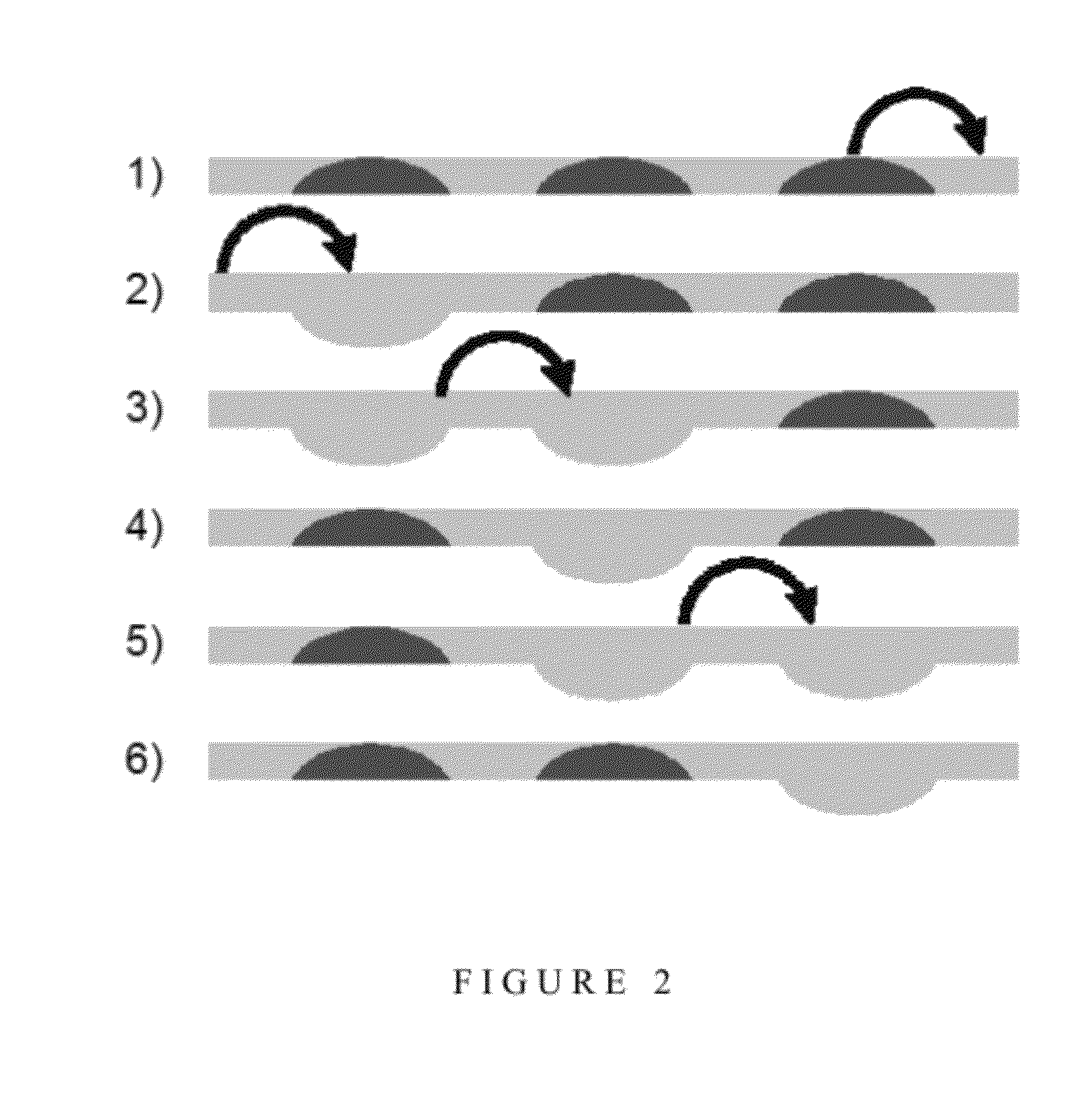
[0124]Use of a Four Valve Peristaltic Pump Rather than a Three Valve Peristaltic Pump Improves the Efficiency of Peristaltic Mixing

[0125]Once the three valve peristaltic pump had been optimised, it was discovered that the use of a fourth valve could make the pumping surprisingly more efficient. As described above, the sequence used with 3 valves can be described analogically with 1 for a valve closed and 0 for a valve opened (111,011,001,101,100,110). If four valves are used, a similar sequence can be used (1111,0111,0011,0001,1001,1000,1100,1110) which is made of 8 steps. Based on three valves, one volume is displaced in 6 steps whereas with 4 valves, there are 2 volumes that are displaced in 8 steps, which theoretically makes it 1.5 times more efficient (2×6 / 8).

[0126]The mixing of water with fluorescein was experimentally observed with a fluorescence microscope. Initially the signal is small when the window is located underneath the water channel, but the fluorescence signal quick...

example 3

[0127]Multiple Mixing Steps with a Single Loop Mixer

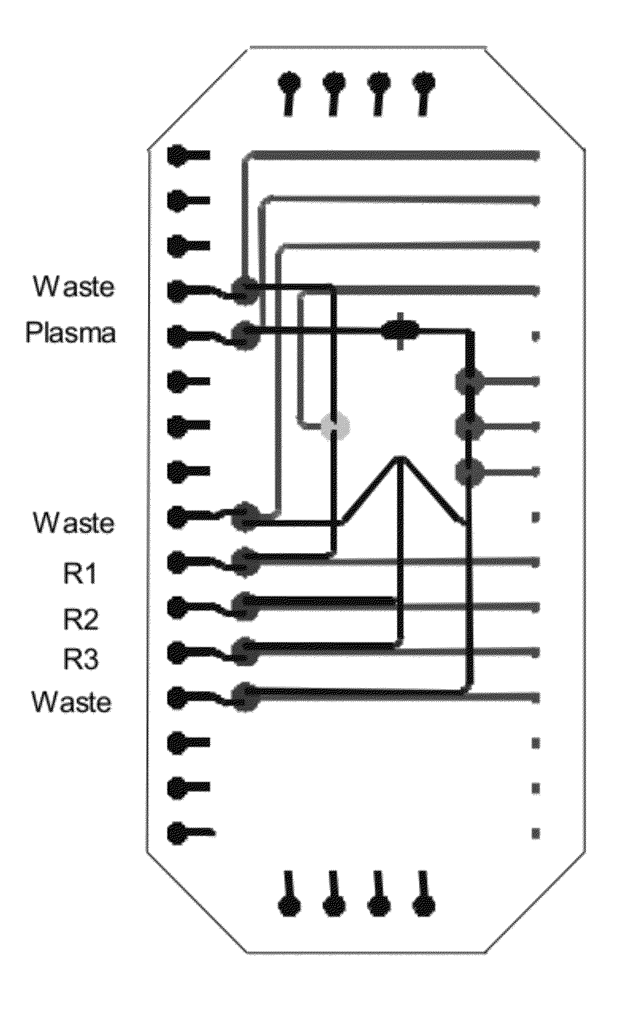
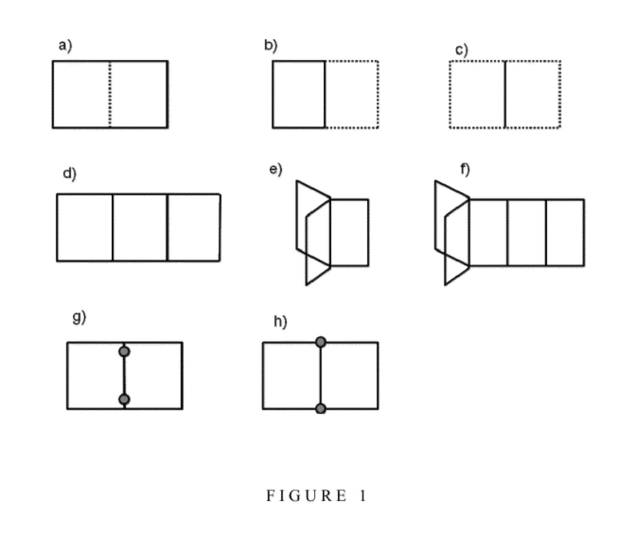
[0128]The ALT assay comprises a two step mixing procedure which is achieved using a loop which is a “square” where two sides are filled with sample, one with reagent 1 and the fourth side with reagent 2. The peristaltic pumps are actuated to mix the three solutions. Pyruvate is removed during this mixing step. Then the activator (reagent 3) is flown into the same fourth side of the square, replacing a quarter of the premixed solution by reagent 3. A further mixing step occurs and then fluorescent decay is measured. The metering of the fluids is achieved by providing channels of appropriate dimensions. The layout shown in FIG. 5 provides a saving in footprint and enables accurate metering. One advantage of this method is that although a portion of the sample is wasted, the waste is accurately controlled. With such a structure, it is easy to implement mixing steps of one volume of reagent 1 to one volume of reagent 2 to two volumes o...


PUM


Abstract

Provided is a microfluidic mixing system comprising a loop system for transferring one or more fluids, wherein the loop system comprises a plurality of sub loops, each sub loop formed from one or more common channels shared with at least one other sub loop and completed by an outer channel portion that is not shared by any other sub loop, and wherein the outer channel portion of each sub loop comprises one or more valves such that the sub loop is capable of isolation from all other sub loops and each common channel comprises one or more valves such that the common channel is capable of isolation from the remainder of the loop system, and wherein one or more sub loops in the system comprise valves that are configured to enable peristaltic mixing.

Description

FIELD OF THE INVENTION[0001]The present invention concerns systems for mixing one or more fluids within a microfluidic device and methods for mixing fluids within a microfluidic device.BACKGROUND OF THE INVENTION[0002]Microfluidic and nanofluidic devices are well known in the art, and are designed to manipulate fluids that are constrained in the microscale or nanoscale respectively. Microfluidic and nanofluidic devices have been used in many different fields which require the use of very small volumes of fluids, including engineering and biotechnology. For example, microfluidic systems have been used in the development of inkjet printheads and DNA chips.[0003]Biological assays usually require various mixing steps. Quite often, successive mixing steps are required and in most methods known in the art it is necessary for a multistep reaction to include manual steps. For example, typical PCR reactions require the person carrying out the reaction to add reagents in multiple stages. Ofte...

Claims


Application Information

Patent Timeline
IPC IPC(8): B01F15/02B81B1/00
CPCB01F5/10B01F5/108B01F11/0045B01F13/1022B01F13/1013B01F13/1016B01F13/0059B01F25/54B01F25/50B01F31/31B01F33/30B01F33/811B01F33/81B01F33/813
Inventor CHAPRON, JULIENPOLWART, STUARTSALMON, JONATHAN
Owner SCI TECH CORP
Why Eureka
Try Eureka