Short oxygen delignification method

a technology of oxygen delignification and oxygen lignification, which is applied in the field of short process of oxygen delignification, can solve the problems of affecting paper production, high capital cost, operating cost and maintenance cost of oxygen delignification tower system, and many millions of dollars in construction cost, so as to achieve rapid and efficient mixing of flowable materials

Inactive Publication Date: 2016-05-05
QUANTUM TECH INC
View PDF2 Cites 5 Cited by
  • Summary
  • Abstract
  • Description
  • Claims
  • Application Information

AI Technical Summary

Benefits of technology

[0007]The present disclosure is directed to a short oxygen delignification method that employs a continuous dynamic mixing assembly which mixes flowable material including an oxygen-containing gas (e.g., including oxygen and / or CO2), a liquid including paper pulp, optional steam and a liquid basic compound. Lignin is bound to the paper pulp. Steam can be used to raise the temperature of the flowable material. A heating source instead of steam can be used, for example, hot oxidized white liquor. The flowable materials may all be mixed together before being directed into the mixing chamber or one or more of the flowable materials may be introduced separately into the mixing chamber. For example, the paper pulp fluid, the optional steam, the basic compound and the oxygen-containing gas may be combined together before entering the mixing chamber. On the other hand, the paper pulp fluid and the optional steam may be combined as a first component, the basic compound may be separately added to this as a second component, which enters the mixing chamber mixed together, and the oxygen-containing gas as a third component may be separately introduced into optional gas inlet ports or insert assemblies into the mixing chamber. Other variations of combinations and components of the flowable materials and manner in which they enter the mixing chamber may also be suitable in this disclosure. The mixing assembly employs axially extending baffles and transverse baffles along with a unique, baffled agitator design that enables very rapid and efficient mixing of the flowable materials carrying out the short oxygen delignification process.
[0008]The mixing assembly used in the method of the present disclosure is particularly well suited for conducting delignification chemical reactions by the combination of the oxygen-containing gas (e.g., including oxygen and / or CO2) and the paper pulp fluid and the liquid basic compound for chemical reaction. When the oxygen-containing gas, the paper pulp liquid, the optional steam and the liquid basic compound are mixed in the mixing chamber, delignification advantageously occurs in a relatively short time interval, using relatively little energy. These and other advantages arise from the interplay of the mixing chamber baffling system and the unique agitator design with baffles causing a high degree of mixing.
[0009]The dynamic mixing assembly used in the method of the present disclosure enables the efficient dispersion, dissolution and reaction when the flowable materials are combined. In the present disclosure the delignification reactions can occur, for example, at least on the order of 15 times faster than in a conventional tower delignification system, with apparatus that is a fraction of the size and capital cost. These and other advantages are obtained by the combination of, inter alia, the design of the axial and transverse baffles and the agitator baffles.
[0011]The design of the agitator baffles, and axial and transverse baffles of the mixing chamber offer numerous advantages and serve a plurality of purposes. The mixing chamber baffle systems disrupt axial and circumferential fluid flow and enable efficient mixing. Referring to axial flow in this disclosure means flow that occurs substantially along the longitudinal axis of the mixing chamber. It should be realized that the fluid flow inside the mixing chamber of this disclosure is complex and reference to inhibiting or disrupting axial fluid flow and circumferential fluid flow are only intended to generally assist in the illustration of the effects of the baffles inside the mixing chamber without unduly limiting the disclosed method. This disclosure and the accompanying drawings should not be taken as a precise explanation of fluid flow and gas flow, and all reaction(s), occuring inside the mixing assembly during the disclosed method. Referring to circumferential fluid flow in this disclosure means non-axial fluid flow fluid flow near the interior wall of the mixing chamber.
[0012]The baffles function especially well with the rotatable agitator having arcuate blades, lobes, threads or the like. For example, the blades can be twisted helical along a cylindrical hub of the shaft of the agitator with a constant height. Another variation employs straight, rather than twisted, blades extending diagonally along a flat surface of the agitator shaft or hub, the blades being arcuate. In the case of the twisted or helical blades, a space between the outermost edge portion of a blade or blade tip and innermost edge of an adjacent axial baffle at their closest distance, exists as each of the blades passes an axial baffle. A twisted blade design along the longitudinal axis enables the blade tips to utilize a sweeping action relative to the inward edges of the axial baffles. Since the blades are twisted, only a small portion of the blade tip is closest to an adjacent axial baffle at one time forming the space. As the agitator rotates, the closest distance between the twisted blade tip and the innermost edge of the axial baffle (i.e., the space) progresses in one direction along a length of the axial baffle in a direction of the longitudinal axis. Once the blade tip of that particular blade reaches an end of a particular segment, the next circumferentially offset twisted blade in that segment now has its closest portion of the blade tip at a start of that axial baffle in that segment. When viewed from a cross-sectional end view, the four blades, for example, in each axial segment each twist for a span of, for example, about 90 degrees. In particular, the blades in the downstream segment can be circumferentially offset in a cross-sectional end view such that the starting location of each of the blades in the downstream axial segment is between the end point of blades in the upstream axial segment. For example, the axial baffles of a downstream axial segment circumferentially offset from the axial baffles of the adjacent upstream axial segment in a cross-sectional end view. That is, the axial baffles of the downstream segment are located between the axial baffles of the upstream axial segment from an end view. The sweeping of the twisted and straight arcuate blades past the axial baffles causes a mixing action and further lessens mixing power consumption. Generally, one point of a blade tip at a time is separated from one point on an adjacent axial baffle edge by the predetermined space, which maximizes mixing efficiency. The flow in the mixing chamber can be increased or retarded based upon the speed and rotational direction of the agitator, in view of its twisted or straight arcuate blade orientation.

Problems solved by technology

The presence of lignin is detrimental to paper making where bright white paper is desired.
The capital cost, operational costs and maintenance costs of the oxygen delignification tower system are very high.
Such a tower costs many millions of dollars to construct.

Method used


Image

  • Short oxygen delignification method
  • Short oxygen delignification method
  • Short oxygen delignification method

Examples


Embodiment Construction

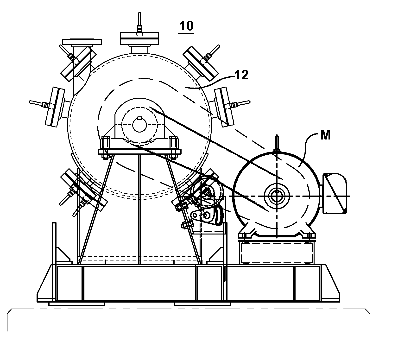
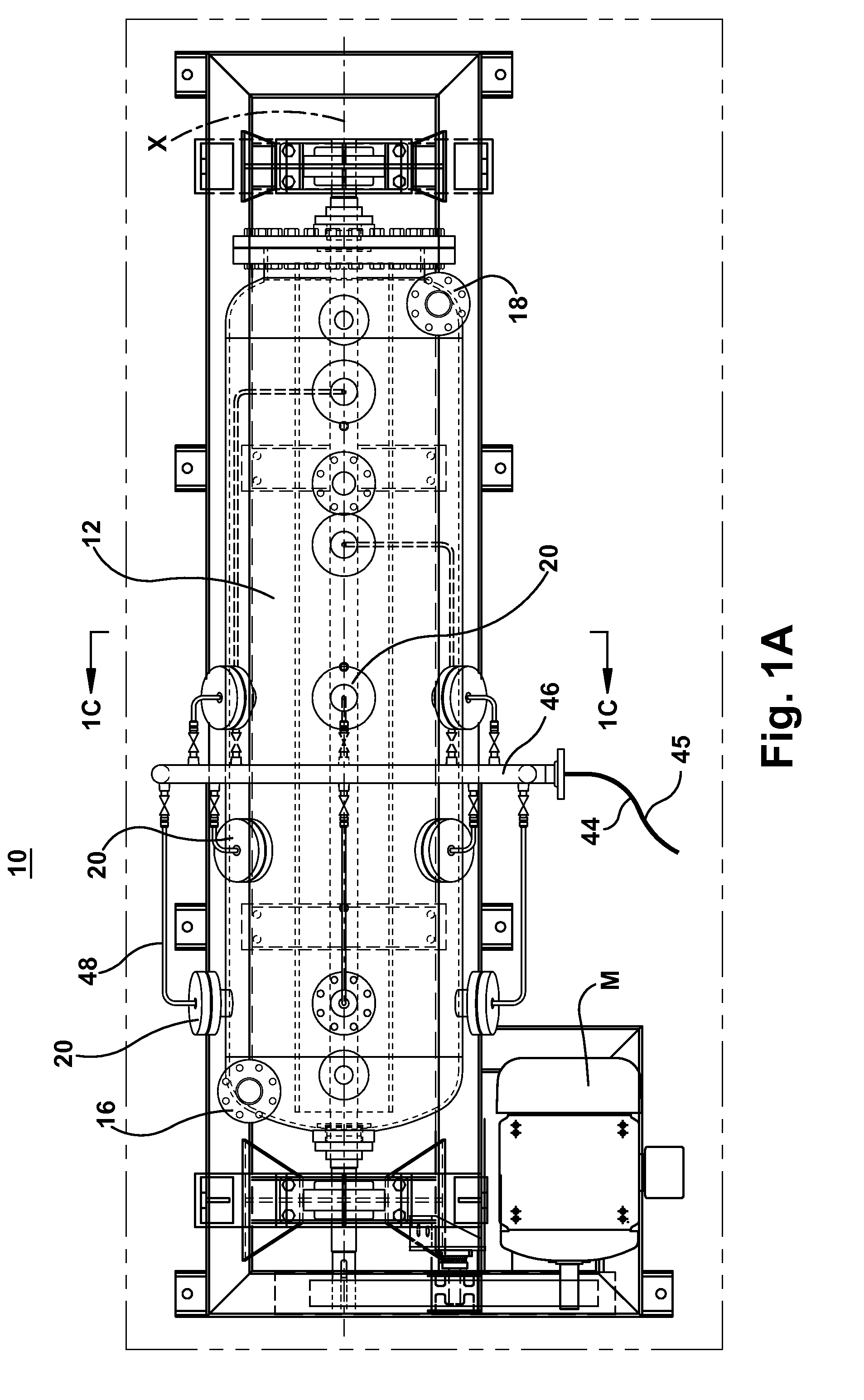
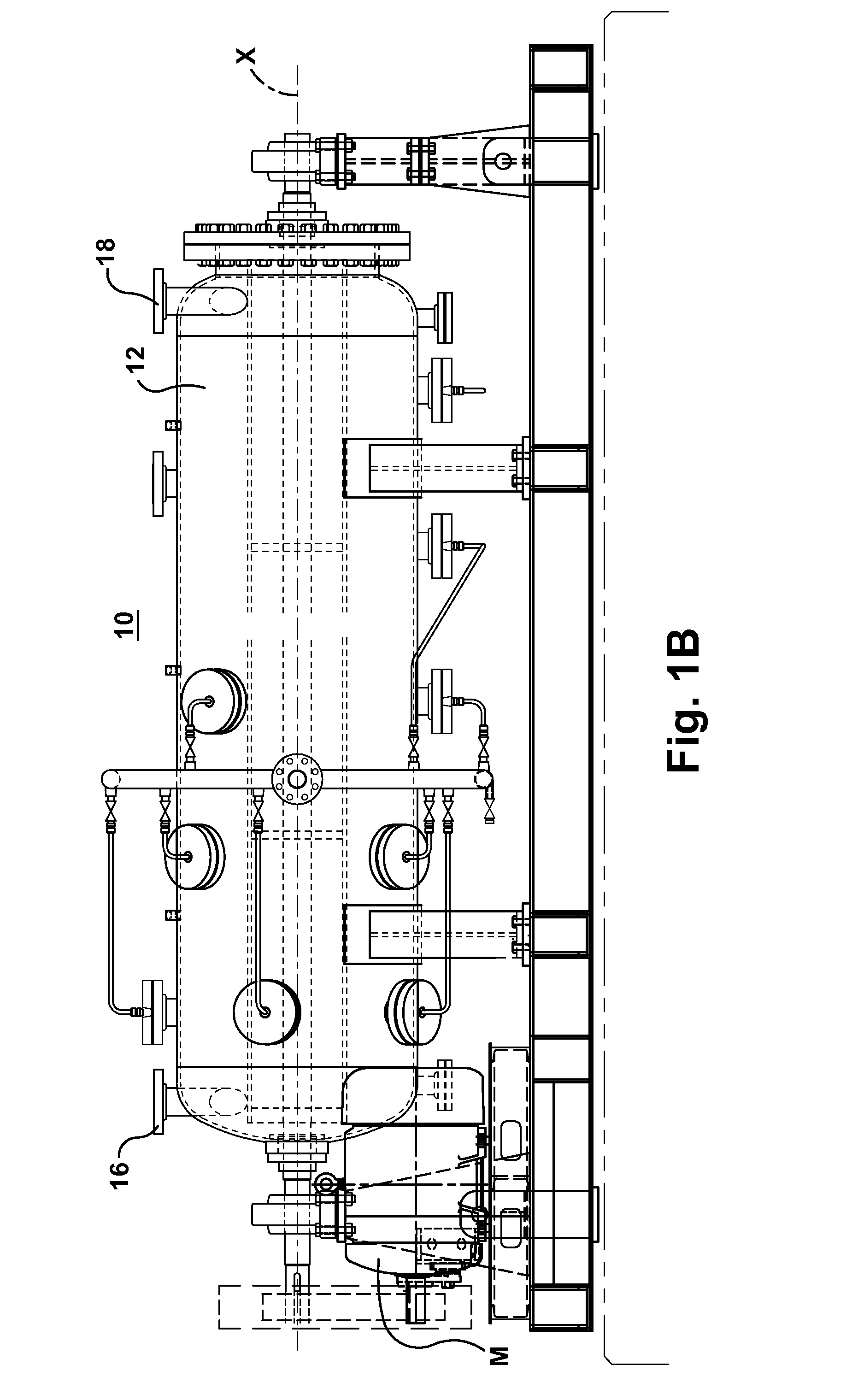
[0035]Referring now to the drawings, a mixing assembly 10 permits mixing of the flowable material, a delignification reaction and lignin dissolving inside the mixing chamber. The flowable material includes paper pulp (a liquid and suspended solids), optional steam (for increasing reaction temperature), a basic compound and an oxygen-containing gas. The basic compound, for example, is selected from the group consisting of oxidized white liquor, sodium hydroxide, sodium bicarbonate, a peroxide compound, ozone, oxidized green liquor and combinations thereof. The mixing assembly comprises a generally cylindrical mixing chamber 12 having an interior wall 13. The mixing chamber is substantially symmetrical about a central longitudinal axis X (FIG. 1). The mixing chamber can be substantially horizontally extending. At least one inlet 16 is connected to the mixing chamber 12 through which the flowable material is introduced into the mixing chamber 12. At least one outlet 18 is connected to ...


PUM

PropertyMeasurementUnit
outer diameteraaaaaaaaaa
angleaaaaaaaaaa
angleaaaaaaaaaa

Abstract

A short oxygen delignification method employs a mixing assembly including a mixing chamber having an interior wall which is generally symmetrical about a central longitudinal axis. At least one inlet is used to introduce paper pulp, a basic compound, optional steam and an oxygen-containing gas into the mixing chamber. At least one axial baffle is connected to and extends along the interior wall. At least one transverse baffle is connected to and extends from the interior wall transverse to the axis. A rotatable agitator includes at least one agitator baffle extending transverse to the axis at a location in alignment with a respective transverse baffle. This forms at least one gap between the at least one agitator baffle and the at least one respective transverse baffle. The paper pulp fluid is forced to travel through the at least one gap. A short delignification reaction occurs inside the mixing chamber. Delignified paper pulp fluid leaves the mixing chamber through at least one outlet of the mixing chamber.

Description

FIELD OF THE INVENTION[0001]The present disclosure relates to a short process of oxygen delignification that occurs after mixing a basic compound, paper pulp and oxygen-containing gas in a continuous dynamic mixing assembly having a unique baffle and agitator design.TECHNICAL BACKGROUND[0002]In some paper pulping processes, a solution referred to as “oxidized white liquor” is used. Oxidized white liquor is typically made by oxidizing reducing compounds found in white liquor such as sodium sulfide, sodium polysulfide and sodium thiosulfate to form an oxidized white liquor having non-reducing compounds such as sodium sulfate therein.[0003]A stirred tank of white liquor and either air or oxygen or a combination thereof and an external heat source is a common method of commercially producing white liquor as disclosed in U.S. Pat. Nos. 5,500,085 and 5,382,322.[0004]Some paper mills, for example, those employing the kraft process, employ one or more oxygen delignification systems for remo...

Claims


Application Information

Patent Timeline
Patent Type & Authority Applications(United States)
IPC IPC(8): D21C7/02D21C3/02D21C1/08D21C1/02B01F7/00B01F15/02
CPCD21C7/02B01F7/00325B01F15/0233B01F15/0274B01F2215/0078D21C1/08D21C1/02D21C3/02B01F15/0248B01F27/0723B01F27/0724B01F27/707B01F27/191
Inventor PIECHUTA, PETER A.YANT, ROBERT E.
Owner QUANTUM TECH INC
Why Eureka
Try Eureka