
Motorized window treatment

a motorized and window treatment technology, applied in the direction of door/window protective devices, curtain suspension devices, high-level techniques, etc., can solve the problems of requiring subsequent repair, high cost of running additional ac main line voltage wiring to the electronic drive unit, and unsatisfactory aesthetics, etc., to achieve the effect of not expensive to replace, easy to clean, and easy to clean

Active Publication Date: 2012-10-18
LUTRON TECH CO LLC
View PDF9 Cites 221 Cited by
  • Summary
  • Abstract
  • Description
  • Claims
  • Application Information

AI Technical Summary

Benefits of technology

The system provides a cost-effective, aesthetically pleasing, and long-lasting battery-powered solution for motorized window treatments with extended battery life and convenient replacement, allowing for wireless control and energy-efficient operation.

Problems solved by technology

Unfortunately, this requires that electrical wires to be run from the power source to the electronic drive unit.
Running additional AC main line voltage wiring to the electronic drive unit can be very expensive, due to the cost of the additional electrical wiring as well as the cost of installation.
In addition, if the pre-existing wiring runs behind a fixed ceiling or wall (e.g., one comprising plaster or expensive hardwood), the electrician may need to breach the ceiling or wall to install the new electrical wiring, which will thus require subsequent repair.
However, this sort of installation requires the permanent use of one of the outlets of the electrical receptacle and is aesthetically unpleasing due to the external electrical wires.
However, the typical prior art battery-powered motorized window treatments have suffered from poor battery life (such as, one year or less), and have required batteries that are difficult and expensive to replace.

Method used


Image

  • Motorized window treatment
  • Motorized window treatment
  • Motorized window treatment

Examples


first embodiment

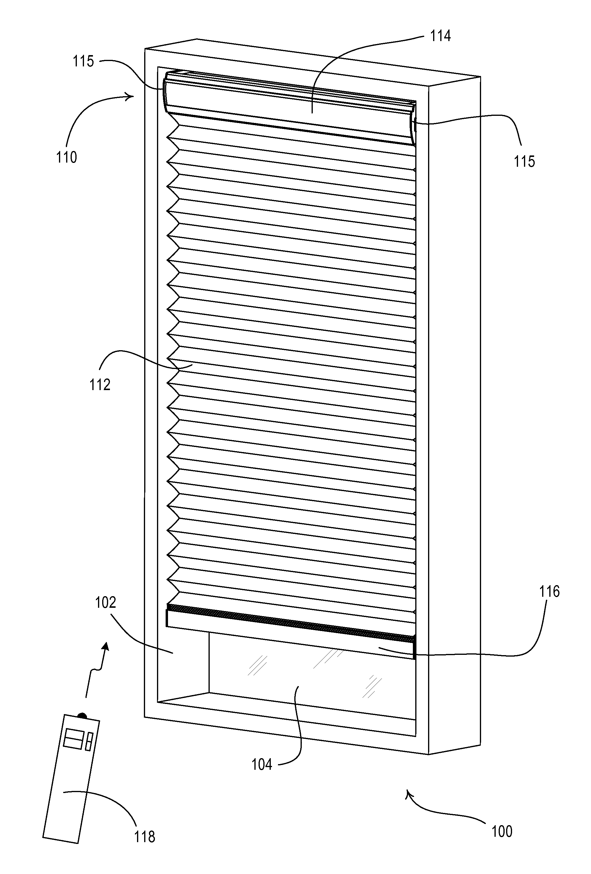
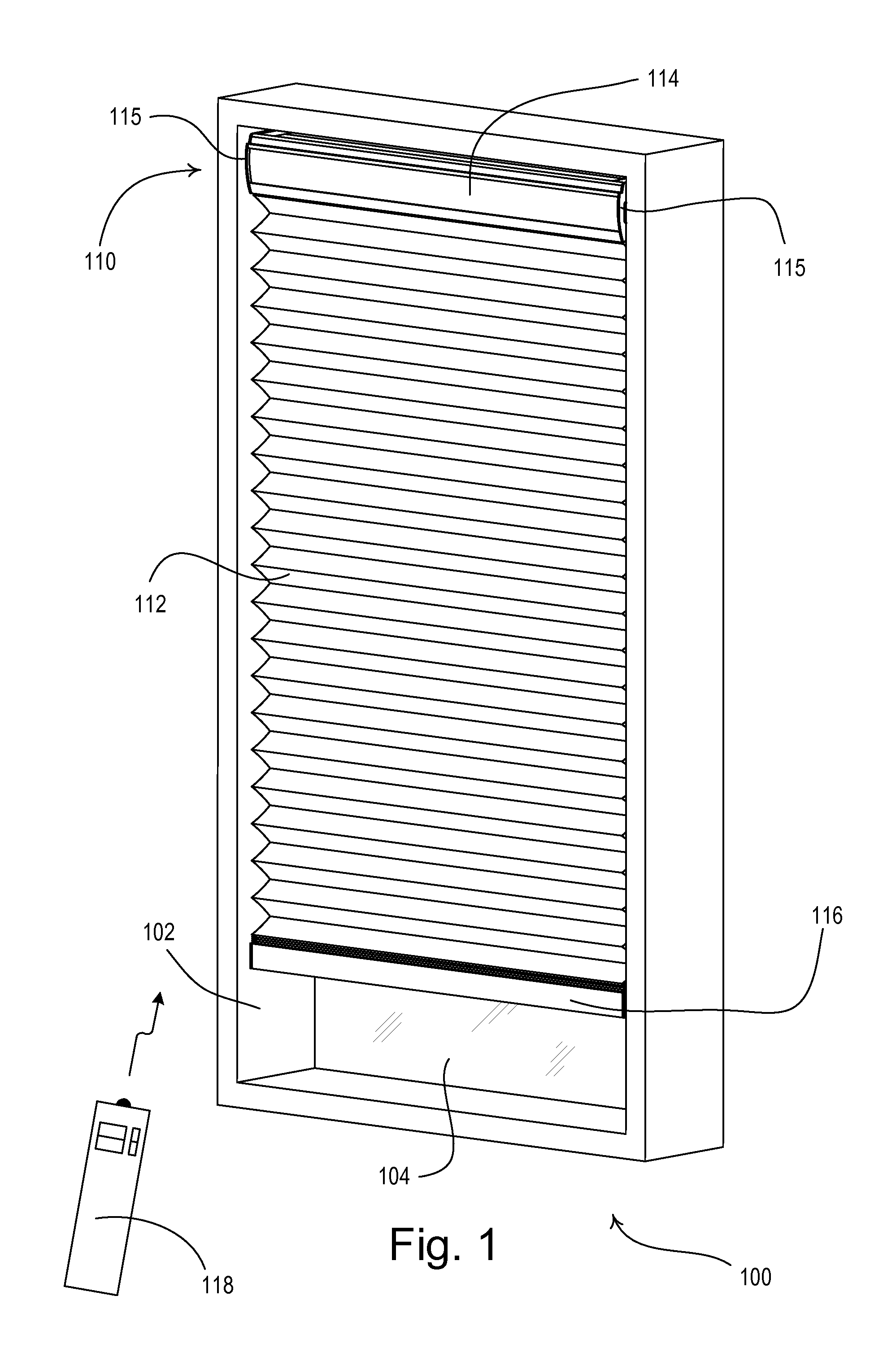
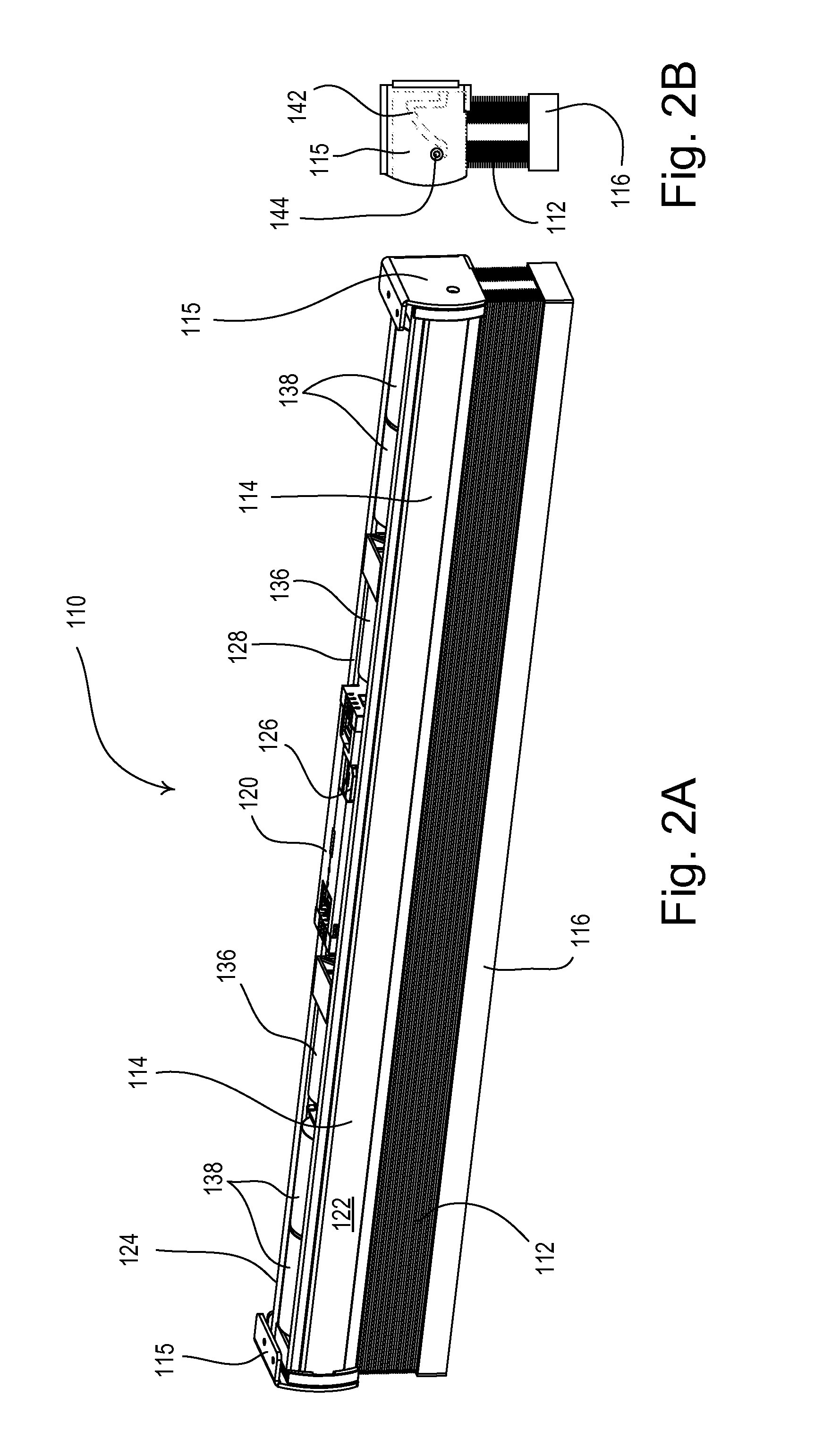
[0084]According to the present invention, the spring assist assemblies 135 are coupled to the drive shafts 132 with one of the spring assist assemblies housed in each of the lift cord spool enclosures 136 as shown in FIG. 3. Each spring assist assembly 135 includes a constant-force spring (not shown) having a first end attached to the respective lift cord spool enclosure 136 (which is fixedly attached to the head rail 114) and a second end attached to the respective drive shaft 132. The spring assist assemblies 135 operate to provide a constant torque (e.g., approximately 0.44 Newtons) on the drive shafts 132 in the direction opposite the direction of the torque provided on the drive shafts by the lift cords 130. For example, the constant amount of torque provided by the spring assist assemblies 135 may be approximately equal to the torque provided on the drive shafts 132 by the lift cords 130 when the weighting element 116 is positioned half-way between the fully-open position PFUL...

second embodiment

[0136]FIGS. 21A and 21B are partial perspective views of the motor drive unit 720 and the headrail 114 of the motorized window treatment 710 of the The antenna 768 is adapted to extend from the motor drive unit 720 and is received in an elongated antenna wire carrier 770. As shown in FIG. 21A, the antenna wire carrier 770 may be located in a first position immediately adjacent the motor drive unit 720 above the external side 124 of the headrail 114. The antenna wire carrier 770 may be removed from the first position and re-located into a second position in which the antenna 768 is slightly offset (e.g., by a distance of approximately 0.4 inch) from the motor drive unit 720 as shown in FIG. 21B. The antenna wire carrier 770 comprises clips 772 that are adapted to snap onto the top edge of the external side 124 of the headrail 114 in the second position. The antenna wire carrier 770 provides a mechanical means for adjusting the RF sensitivity of the RF receiver 766 and thus the power...

third embodiment

[0158]According to the present invention, one of the signal repeaters (e.g., signal repeater 1060A) operates as a “main” repeater (i.e., a main controller) to facilitate the operation of the load control system 1000. The main repeater 1060A has a database, which defines the operation of the load control system, stored in memory. For example, the main repeater 1060A is operable to determine which of the lighting load 1032 is energized and to use the database to control any visual indicators of the dimmer switch 1030 and the keypads 1042, 1040 accordingly to provide the appropriate feedback to the user of the load control system 1000. In addition, the control devices of the load control system may be operable to transmit status information to the signal repeaters 1060A, 1060B. For example, the motor drive unit 1020 of each of the motorized window treatments 1010 may be operable to transmit a digital message representative of the magnitude of the respective battery voltage to the signa...


PUM


Abstract

A motorized window treatment controls daylight entering a space through a window and includes a covering material, a drive shaft, lift cords received around the drive shaft and connected to the covering material, and a motor coupled to the drive shaft. It also includes a spring assist unit for the motor providing a torque that equals the torque provided by the weight on the lift cords at a position midway between fully-open and fully-closed positions, minimizing motor usage and conserving battery life. A photosensor for measuring the daylight outside the window and temperature sensors for measuring the temperatures inside and outside of the window may be provided. The position of the covering material is automatically controlled to save energy, or may also be controlled in response to an infrared or radio-frequency remote control.

Description

CROSS REFERENCES TO RELATED APPLICATIONS[0001]This application is a non-provisional application of commonly-assigned U.S. Provisional Application No. 61 / 451,960, filed Mar. 11, 2011; U.S. Provisional Application No. 61 / 530,799, filed Sep. 2, 2011; and U.S. Provisional Application No. 61 / 547,319, filed Oct. 11, 2011, all entitled MOTORIZED WINDOW TREATMENT, the entire disclosures of which are hereby incorporated by reference.BACKGROUND OF THE INVENTION[0002]1. Field of the Invention[0003]The present invention relates to a motorized window treatment, and more specifically, to a low-cost, quiet, battery-powered motorized window treatment that is characterized by an ultra-low power consumption that makes battery power more convenient for a user and results in long and practical battery lifetimes. In addition, the present invention relates to a battery-powered motorized window treatment that is controlled in response to wireless input signals and may be installed without requiring any ad...

Claims


Application Information

Patent Timeline
Patent Type & Authority Applications(United States)
IPC IPC(8): E05F15/20H02K7/14H02K7/10A47H5/032
CPCE06B9/32E06B9/322E06B9/62E06B2009/2625E06B2009/6818E06B9/70Y02B80/50Y02B60/50H04W52/0238H04W52/0245H04W52/0287E06B2009/6872Y02B80/00Y02D30/70E06B9/68Y02A30/24H04W52/0216H04W52/0219H04W52/0229H04W52/028H04W52/0235H04W52/0225E06B9/38E06B9/72
Inventor ADAMS, JASON O.MIERTA, JUSTIN J.MISTARZ, DANIEL W.NEWMAN, JR., ROBERT C.OGDEN, JR., PETER W.ROE, JONATHAN L.WU, CHEN MINGZERNHELT, JUSTIN M.BLAIR, EDWARD J.COONEY, ANDREW KARLJAIN, SOUMYAKIRBY, DAVID A.LUNDY, STEPHEN
Owner LUTRON TECH CO LLC
Learn More