Bundle of roving yarns, method of manufacturing a bundle of roving yarns and method for manufacturing a work piece

a technology of roving yarn and bundle, which is applied in the field of method of manufacturing bundle of roving yarn and method of manufacturing work piece, can solve the problems of high final product cost and large labour force, and achieve the effects of low cost, fast production rate and convenient and fast manufacturing method

Inactive Publication Date: 2012-10-18
SIEMENS AG
View PDF10 Cites 0 Cited by
  • Summary
  • Abstract
  • Description
  • Claims
  • Application Information

AI Technical Summary

Benefits of technology

[0020]An alternative method for manufacturing a work piece comprises the steps of placing at least one previously described bundle of roving yarn which comprises thermoplastic material in a mould and thermosetting the thermoplastic material. The thermosetting is performed by consolidating the material by initial heating and melting the thermoplastic material, followed by cooling the material In order to melt the thermoplastic material, the thermoplastic fibres mixed with reinforcement fibres may be heated, to for example 200° C. Then, the liquid thermoplastic material may flow in between the reinforced fibres, for example under vacuum. When cooled and solidified, the work piece is finished. This method provides a cheap and easily performable method for manufacturing a longitudinal unidirectional fibre material.
[0021]The work piece is manufactured by one of the previously described methods. The work piece may be manufactured at comparably low costs since expensive woven fibre material may be replaced by bundles of roving yarn.
[0022]A fast production rate may be obtained with bundles instead of single roving laid in the mould. Moreover, an improved linear fibre orientation is obtained as no stitching yarns are creating waviness or resin rich pockets. Furthermore, a faster impregnation of the fibres may be done, due to a proper combination of vacuum channels and capillary forces. Laminates with extremely high stiffness (E-Modulus) may be fabricated.

Problems solved by technology

This requires much labour force, and leads to high cost of the final product.

Method used


Image

  • Bundle of roving yarns, method of manufacturing a bundle of roving yarns and method for manufacturing a work piece
  • Bundle of roving yarns, method of manufacturing a bundle of roving yarns and method for manufacturing a work piece
  • Bundle of roving yarns, method of manufacturing a bundle of roving yarns and method for manufacturing a work piece

Examples


Embodiment Construction

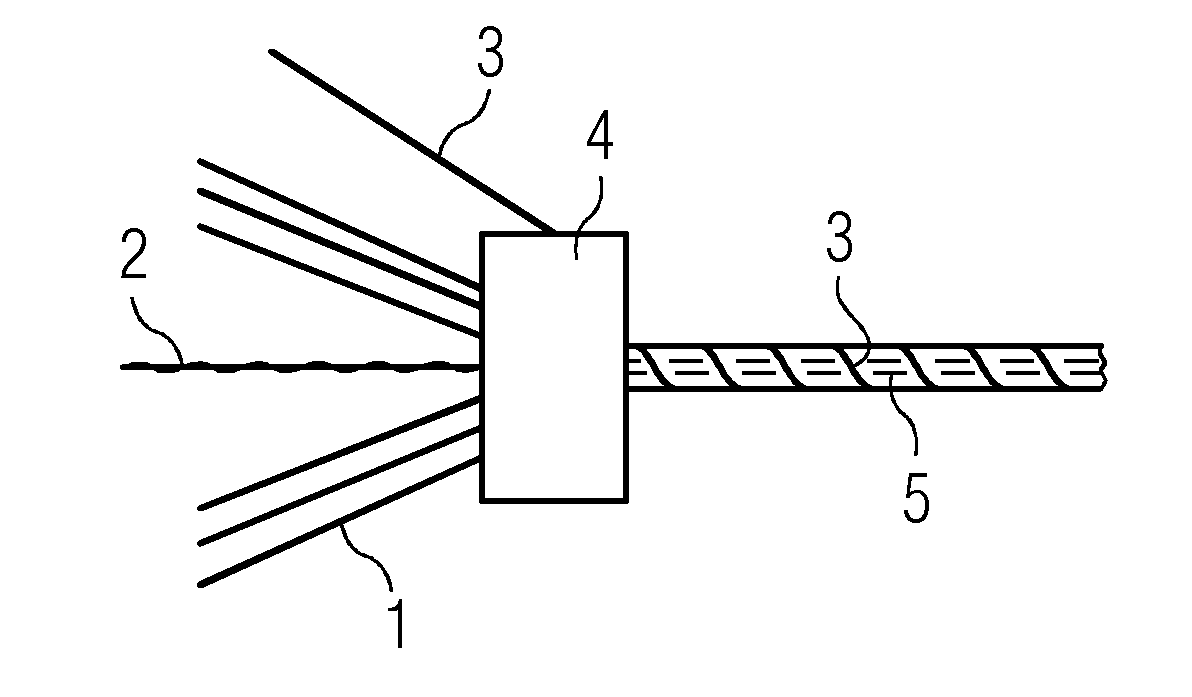
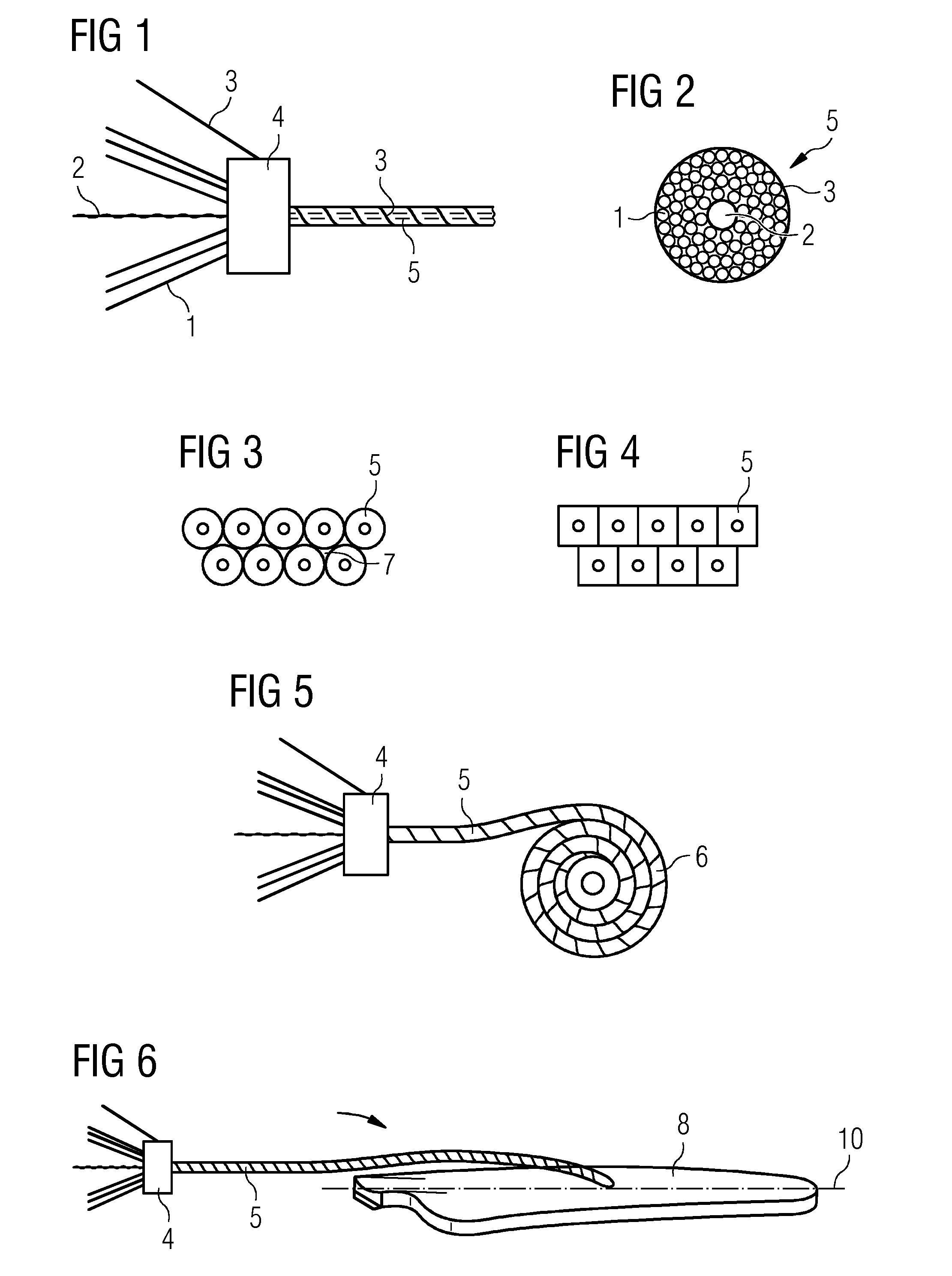
[0039]A first embodiment will now be described with reference to FIGS. 1 to 6. FIG. 1 schematically shows the method for manufacturing a bundle of roving yarns. A number of roving yarns 1 and a central resin flow yarn 2 are assembled in a bundle of rovings 5 by means of a winding apparatus 4. An additional wrapping yarn 3 is circumferentially winded about the bundle of rovings 5 by means of the winding apparatus 4.

[0040]The roving yarn 1 may comprise glass fibre, carbon fibre, basalt fibre, aramid fibre or nature fibre, for example from wood or plants. The roving yarn 1 comprises longitudinal unidirectional reinforced fibres. The bundle 5 may comprises at least 10 roving yarns 1. However, more roving yarns 1 such as 10 to 100 roving yarns 1 may be used. The wrapping yarn 3 may be an elastic yarn. This allows the bundle 5 to change its round shape when placed in a mold, so that all bundles 5 fit with no air voids between the bundles. Yarns 3 that are not elastic may although be fores...


PUM

PropertyMeasurementUnit
sizeaaaaaaaaaa
strengthaaaaaaaaaa
permeabilityaaaaaaaaaa

Abstract

A method of manufacturing a bundle of roving yarns is described. The method is characterised in assembling a number of roving yarns of longitudinal unidirectional fibres and an additional component in a bundle. For example, at least one resin distribution means or a thermoplastic material may be placed as the additional component in the bundle.

Description

CROSS REFERENCE TO RELATED APPLICATIONS[0001]This application claims priority of European Patent Office application No. 1162812.9 EP filed Apr. 18, 2011. All of the applications are incorporated by reference herein in their entirety.FIELD OF INVENTION[0002]The present invention is related to a method of manufacturing a bundle of roving yarns, to a bundle of roving yarns and to the use of such bundles of roving yarns. It is further related to a method for manufacturing a work piece, for example a wind turbine rotor blade, and to a work piece.BACKGROUND OF INVENTION[0003]Fibre reinforced plastic composites are used in a variety of technical products such as cars, wind turbine blades, storage tanks etc. Most products of big size, such as wind turbine blades are manufactured by placing woven glass fabric, delivered on rolls, into one or more moulds. In the common resin injection process known as Vacuum Assisted Resin Transfer Moulding (VARTM), the moulds are closed, and vacuum is applie...

Claims


Application Information

Patent Timeline
Patent Type & Authority Applications(United States)
IPC IPC(8): B29C70/48B29C70/16
CPCB29C70/20B29B15/12B29C70/547B29C70/48Y02E10/74D02G3/402D02G3/36D02G3/02D06M15/00
Inventor GROVE-NIELSEN, ERIK
Owner SIEMENS AG
Why Eureka
Try Eureka