LDO with improved stability

a voltage regulator and stability technology, applied in the direction of electrical variable regulation, process and machine control, instruments, etc., can solve the problems of complex and thus costly schemes, ldos easily become unstable, and bond wires are used

Active Publication Date: 2012-10-18
DIALOG SEMICONDUCTOR GMBH
View PDF7 Cites 18 Cited by
  • Summary
  • Abstract
  • Description
  • Claims
  • Application Information

AI Technical Summary

Benefits of technology

[0012]It is an object of at least one embodiment of the present invention to provide a low drop-out voltage regulator and a method to mimic the external equivalent series resistance of the bond wire.

Problems solved by technology

However, the move to advanced package types will mean that no bond wires are used where these LDOs easily become unstable.
Many solutions to the above problems associated with unstable LDOs have been proposed in the related art, many with complex and thus costly schemes.
This technique however does not address the above mentioned problem with the very low resistances that are associated with the absence of bond wires.

Method used


Image

  • LDO with improved stability
  • LDO with improved stability
  • LDO with improved stability

Examples


case 1

[0033] One solution is to place a series resistor between the pass device and the output Vout, artificially increasing the equivalent ESR. However, this fix will impact the drop-out voltage of the LDO and the load-transient behavior. For output load models we have assumed an equivalent ESR of 100 mΩ. With this ESR, a simulation run shows that the LDO has a phase-margin of about 40° at 100 mA output current, Vout=2.4V and Vdd=3V. If this ESR is reduced to the unlikely case of 1 mΩ, then this phase margin falls to about −5°.

[0034]Referring to FIG. 3a, we show a graph of a computer simulation of Case 1 and an ESR of 100 mΩ with Vout=2.4V and Vdd=3V, for an output current of 100 mA as described above. The horizontal axis displays frequency in Hz ranging from 10−1 to 107. The vertical axis displays Y0 in db for output and Y1 in degrees for the phase. Curve 1 shows the magnitude of the output signal Vout, Curve 2 shows the phase. At Vout=0 the phase margin is 31.47° i.e. the circuit is st...

case 2

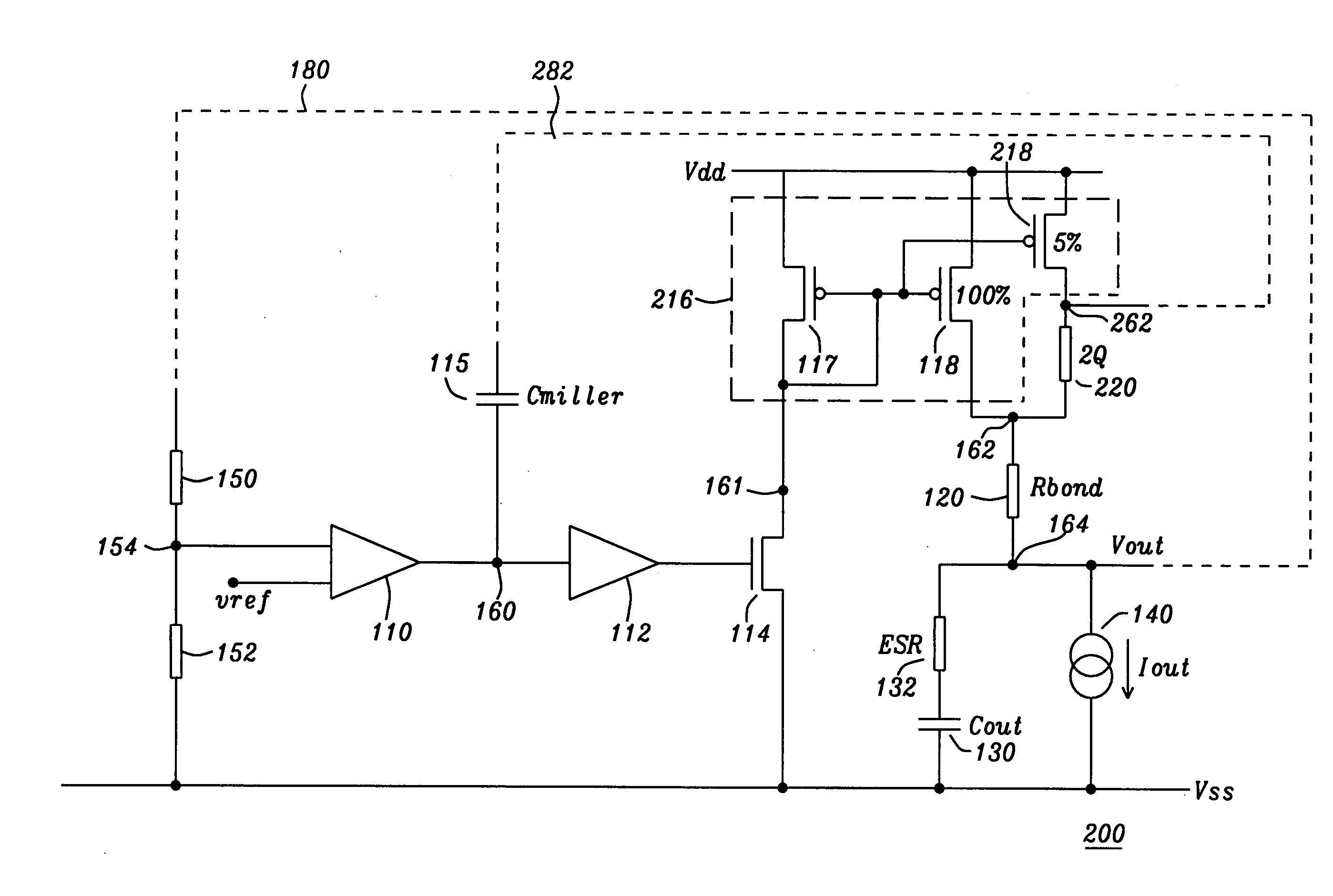
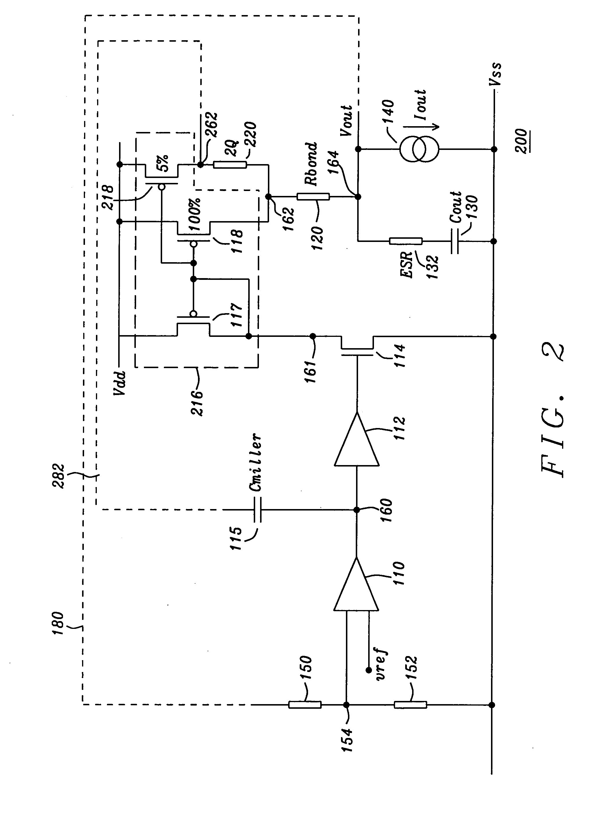
[0036] In the preferred embodiment of the present invention, and referring to FIG. 2, we propose to add another pass device in parallel with the main pass device. A more detailed description of this new circuit follows below. This pass device 218 would be typically about 5% of the existing 100% channel width of the main pass 118 device, but pass device 218 may range from between about 1 to 10% but preferably ranges from between about 0.5 to 15% of the existing channel width of the main pass device. The new pass device will share the power connection and the gate connection. However, between the drain and the output of the LDO is placed a resistor of typically about 2 Ω but which may range from between about 1 to 5 Ω but preferably ranges from between about 0.5 to 10 Ω. The Miller capacitor is now connected to the drain of this new pass device. This means the Miller capacitor sees a much greater ESR, and so it amplifies the fast feedback loop gain, moving the zero node back within th...


PUM


Abstract

A low drop-out (LDO) voltage regulator which parallels a second pass device to a first pass device, where the second pass device has in series a small resistor. The small value resistor is a substitute for bond wires or capacitors with very low equivalent series resistances (ESR). A fast feedback loop is coupled to the junction of the second pass device and the small resistor and provides, via a Miller capacitor, a feedback signal to the amplifier of the voltage regulator. The added second pass device returns circuit stability by moving the fast-loop high frequency zero node back within the bandwidth of the circuit.

Description

BACKGROUND OF THE INVENTION[0001]1. Field of the Invention[0002]The invention relates to a low drop-out (LDO) voltage regulator, and more particularly to eliminating stability problems for LDOs with very low bond wire resistance or no bond wires at all.[0003]2. Description of the Related Art[0004]Currently, low drop-out (LDO) voltage regulators which use advanced techniques usually require that the bond wire impedance is within a reasonably tightly controlled range in order that the LDO is stable. However, the move to advanced package types will mean that no bond wires are used where these LDOs easily become unstable. Many solutions to the above problems associated with unstable LDOs have been proposed in the related art, many with complex and thus costly schemes. Reference is made to U.S. Pat. No. 6,856,124, entitled “LDO Regulator With Wide Output Load Range And Fast Internal Loop” issued Feb. 15, 2005 and assigned to the assignee of this application. That patent shows a method an...

Claims


Application Information

Patent Timeline
Patent Type & Authority Applications(United States)
IPC IPC(8): G05F1/59
CPCG05F1/575G05F3/26G05F1/59
Inventor CHILDS, MARK
Owner DIALOG SEMICONDUCTOR GMBH
Why Eureka
Try Eureka