Fine particle detection system

a detection system and fine particle technology, applied in the direction of instruments, machines/engines, mechanical equipment, etc., can solve the problems of signal current error, signal current error, superimposed external electromagnetic noise, etc., and achieve the effect of low intensity

Active Publication Date: 2012-10-18
NGK SPARK PLUG CO LTD
View PDF8 Cites 41 Cited by
  • Summary
  • Abstract
  • Description
  • Claims
  • Application Information

AI Technical Summary

Benefits of technology

[0004]The signal current of the fine particle detection system, which is responsive to the amount of fine particles in the exhaust gas, is very low in intensity during normal operations of the internal combustion engine. For example, the signal current of the fine particle detection system...

Problems solved by technology

At the generation of aerial discharge, however, there may arise an error in the signal current in the occurrence of a so-called leakage current from any structural component or wiring line of the fine particle detection system.
There may also arise an error in the signal current upon superimposing of exte...

Method used


Image

  • Fine particle detection system
  • Fine particle detection system
  • Fine particle detection system

Examples


Embodiment Construction

[0016]The present invention will be described below in detail with reference to the drawings.

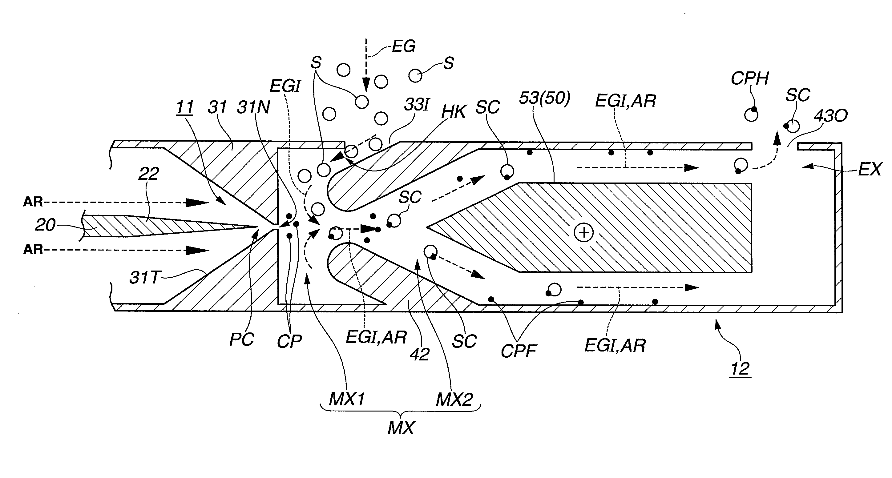
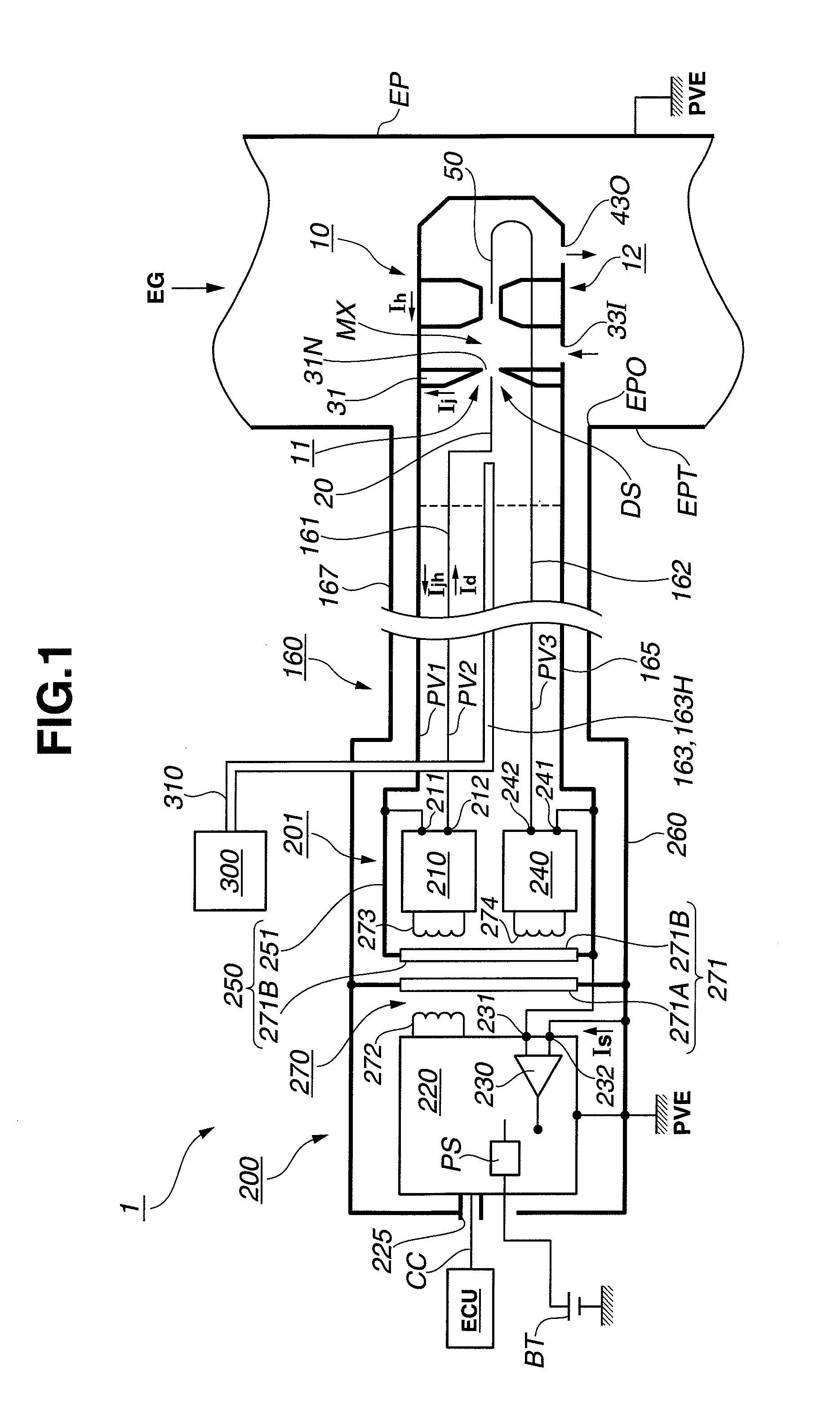
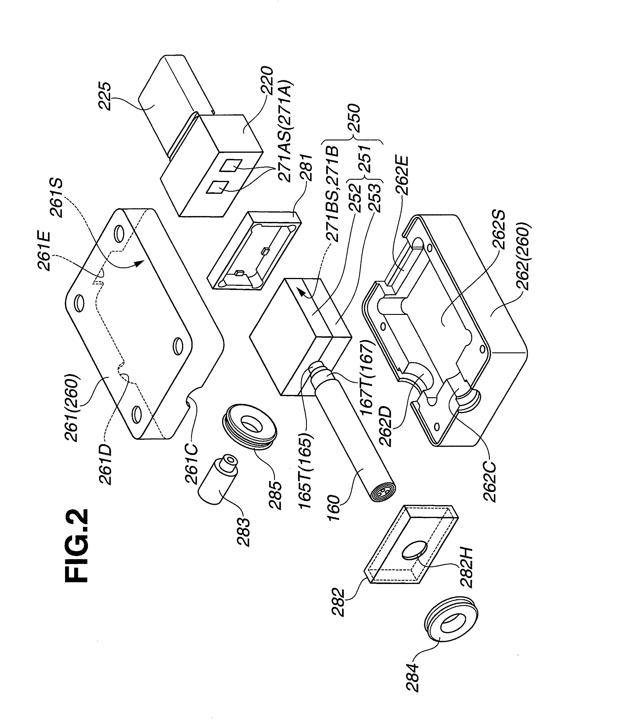
[0017]Referring to FIG. 1, the following embodiment of the present invention refers to a fine particle detection system 1 for detecting the amount of fine particles in exhaust gas EG flowing through a metallic exhaust pipe EP of an internal combustion engine in a vehicle. The fine particle detection system 1 generally includes a fine particle sensor 10 mounted by insertion into a sensor mounting portion EPT of the exhaust pipe EP, a cable 160 extending from the fine particle sensor 10, a sensor drive control device 200 connected to the cable 160 and a transfer pump 300 connected to the cable 160.

[0018]It is herein noted that: in the following description, the terms “front” and “rear” are used with respect to the direction of insertion of the fine particle sensor 10 into the exhaust pipe EP; and some of the drawings are simplified by e.g. omitting the circuit wiring or illustrating the circui...


PUM


Abstract

There is provided a fine particle detection system with a fine particle sensor, a cable and a sensor drive control device. The fine particle sensor has an ion source unit with first and second electrodes, a particle charging unit and inner and outer sensor casings. The cable has a power supply wiring line connected to the second electrode, an inner shield line electrically continuous with the inner sensor casing and an outer shield line electrically continuous with the outer sensor casing. The sensor drive control device has an ion-source power supply circuit, a signal current detection circuit, an inner circuit casing electrically continuous with a first output terminal of the ion-source power supply circuit and surrounding the ion-source power supply circuit and an outer circuit casing connected to the ground potential and shielding the ion-source power supply circuit, the signal current detection circuit and the inner circuit casing.

Description

BACKGROUND OF THE INVENTION[0001]The present invention relates to a fine particle detection system for detecting the amount of fine particles such as soot in exhaust gas flowing through an exhaust pipe.[0002]Fine particles such as soot are contained in exhaust gases of internal combustion engines (e.g. diesel engines and gasoline engines). It is common practice to purify the exhaust gas by collecting the fine particles from the exhaust gas with the use of a filter. It is also feasible to heat the filter to a high temperature that the collected fine particles can be burned off from the filter.[0003]In the event of a deterioration or defect (e.g. breakage) in the filter, the unpurified exhaust gas is directly discharged downstream of the filter. There is thus a demand for a fine particle detection system capable of detecting the amount of fine particles in exhaust gas in order to directly measure the amount of fine particles in the exhaust gas (unpurified exhaust gas) and to detect th...

Claims


Application Information

Patent Timeline
IPC IPC(8): G01N27/66
CPCG01N15/0656F01N2560/05
Inventor MATSUOKA, TOSHIYAMOTOMURA, MASAYUKISUGIYAMA, TAKESHITASHIMA, KEISUKEYOKOI, HITOSHI
Owner NGK SPARK PLUG CO LTD
Why Eureka
Try Eureka