Method and apparatus for priming an extracorporeal blood circuit

a technology of extracorporeal blood and circuit, which is applied in the direction of suction devices, other medical devices, and receipt systems, etc., can solve the problems of increased work hours, increased work hours, and extra work for operators, so as to facilitate the operator's task, avoid recirculating stage, and reduce work time and error risk

Active Publication Date: 2012-10-18
GAMBRO LUNDIA AB
View PDF5 Cites 50 Cited by
  • Summary
  • Abstract
  • Description
  • Claims
  • Application Information

AI Technical Summary

Benefits of technology

[0010]An advantage of the invention is that it facilitates the operator's task during the readying stage of the priming configuration, with a reduction in work times and risk of error.
[0011]A further advantage is that it avoids a recirculating stage during the priming procedure. This reduces the risk of backflow of air which has been already expelled from the dialyser chamber.
[0012]These aims and more besides are all attained by the invention as it is characterised in one or more of the appended claims.
[0013]The priming fluid used can be water or a fluid which is isotonic to human blood, for example an isotonic saline solution or a dialysate or a still further liquid.
[0014]Moreover we describe herein below a solution to the problem of detachment of the air bubbles internally of the hollow fibres which form the semi-permeable membrane of a dialyser or a hemo(dia)filter during a priming procedure. In particular reference is made to a dialyser or a hemo(dia)filter of a type having a bundle of hollow fibres. In particular the blood chamber of the dialyser or hemo(dia)filter comprises an inside volume of the hollow fibres of a hollow fibre bundle, while the fluid chamber (dialysate chamber and / or filtered fluid chamber) comprises the volume comprised between the external side of the hollow fibres and a casing which closes the hollow fibre bundle. It is known that the process of priming an extracorporeal circuit has the aim of eliminating the air contained in the circuit before connecting the circuit to the patient for the dialysis or hemo(dia)filtration treatment. To guarantee complete detachment of the air bubbles during the priming procedure a method and an apparatus are provided for priming a dialyser or hemo(dia)filter according to a further invention, of which a detailed description is provided herein below. In a first embodiment the priming method comprises the following stages: providing a dialyser or a hemo(dia) filter having a blood chamber defined by the internal volume of the hollow fibres of a bundle of hollow fibres; connecting to the blood chamber at least a blood line; connecting to the blood line at least a blood pump; connecting to the blood chamber a source of a priming fluid; activating the pump in order to displace the priming fluid from the source thereof to the blood chamber, the blood pump being activated intermittently based on two (or three, or more than three) preset values corresponding to different activation velocities of the blood pump, the intermittent action causing variations of speed in the priming fluid flow, in order to detach air bubbles from the internal side of the hollow fibres. The variation of speed in the priming fluid flow causes the detachment of air bubbles from the internal side of the hollow fibres. The variation of speed in the priming fluid flow shall be relatively brusque. Said speed variation shall be sufficiently brusque to cause said air bubble detachment. The sharpness of the speed variation will depend on, inter alia, the type of the hollow fibre bundle. In a second embodiment, the source of priming fluid of the first embodiment can be connected to the blood chamber in order that the blood chamber is arranged between the source of a priming fluid and the blood pump. In further embodiments, the blood pump of the first or the second embodiments can be activated in order to displace the priming fluid from the source thereof to the blood chamber and thereafter from the blood chamber to an inlet of the blood pump. With reference to all of the preceding embodiments, at least one of the above preset values can also correspond to a nil velocity of priming fluid flow. With reference to all of the preceding embodiments, the above-mentioned preset values correspond to displacements of the priming fluid at various speeds (one of which could be a nil velocity) from the source thereof to the blood chamber and thereafter from the blood chamber to an inlet of the blood pump. With reference to all the preceding embodiments, the source of the priming fluid can comprise a container of priming fluid connected to the blood chamber and / or a back-filtration flow which originates in the dialyser or hemo(dia)filter fluid chamber and which flow through the semipermeable membrane. With reference to all of the preceding embodiments, the blood pump can comprise a tube-deforming pump, for example a rotary pump. With reference to all of the preceding embodiments, at least two of said preset values correspond to different or equal activation velocities of the blood pump in the same direction. In a first embodiment thereof the priming apparatus comprises: a dialyser or hemo(dia)filter having a blood chamber defined by the internal volume of the hollow fibres of a bundle of hollow fibres; at least a blood line connected to the blood chamber; at least a blood pump connected to the blood line; at least a source of a priming fluid, connected to the blood chamber; a control unit programmed to activate the blood pump in order to displace the priming fluid from the source of a priming fluid to the blood chamber, the blood pump being activated intermittently, based on two (or three, or more than three) preset values corresponding to different activating velocities of the blood pump, the intermittent activation causing (brusque) variations of velocity of the priming fluid flow, so as to detach air bubbles from the internal side of the hollow fibres. In a second embodiment of the apparatus, the source of a priming fluid of the first embodiment can be connected to the blood chamber in order for the blood chamber to be arranged between the source of a priming fluid and the blood pump. In further embodiments of the priming apparatus, the control unit can be programmed so that the blood pump of the first or second embodiment is activated in order to displace the priming fluid from the source of a priming fluid to the blood chamber, and thereafter from the blood chamber to an inlet of the blood pump. With reference to all the preceding embodiments, at least one of the above-mentioned preset values can also correspond to a nil flow velocity of the priming fluid. With reference to all the preceding embodiments, the above-mentioned values correspond to priming fluid displacements at various speeds (one of which could be nil) from the source of a priming fluid to the blood chamber and, thereafter, from the blood chamber to an inlet of the blood pump. With reference to all the preceding embodiments, the priming fluid source can comprise a container of priming fluid connected to the blood chamber, and / or a back-filtration flow which originates in the dialyser or hemo(dia)filter fluid chamber and which crosses the semipermeable membrane, the apparatus comprising means for back-filtration commanded by the control unit, specially programmed for this purpose. With reference to all the preceding embodiments, the blood pump can comprise a tube-deforming pump, for example a rotary pump. With reference to all of the preceding embodiments, at least two of said preset values correspond to different or equal activation velocities of the blood pump in the same direction of the blood pump. The above-described embodiments, relating to a method and an apparatus, in reference to the further invention which solves the problem of the complete detachment of air bubbles, can all be combined in all the embodiments of method and apparatus which have been and which will be described in the present application, with reference to the first invention, which is directed at resolving the problem of the discharge of the priming fluid.
[0015]Further characteristics and advantages of the present invention will better emerge from the detailed description that follows, of various embodiments of the invention, illustrated purely by way of non-limiting example in the accompanying figures of the drawings.

Problems solved by technology

One of the drawbacks of the method described in WO 96 / 40320 is the risk of contamination of the extracorporeal blood circuit by contaminating agents originating from the discharge port, especially in the recirculating stage.
A further drawback consists in the special care and attention the operator must take during the apparatus readying stage of the apparatus in the priming configuration, with a consequent increase in work times, extra work for the operator, the need to have well-trained operators and the risk of error.

Method used


Image

  • Method and apparatus for priming an extracorporeal blood circuit
  • Method and apparatus for priming an extracorporeal blood circuit
  • Method and apparatus for priming an extracorporeal blood circuit

Examples


Embodiment Construction

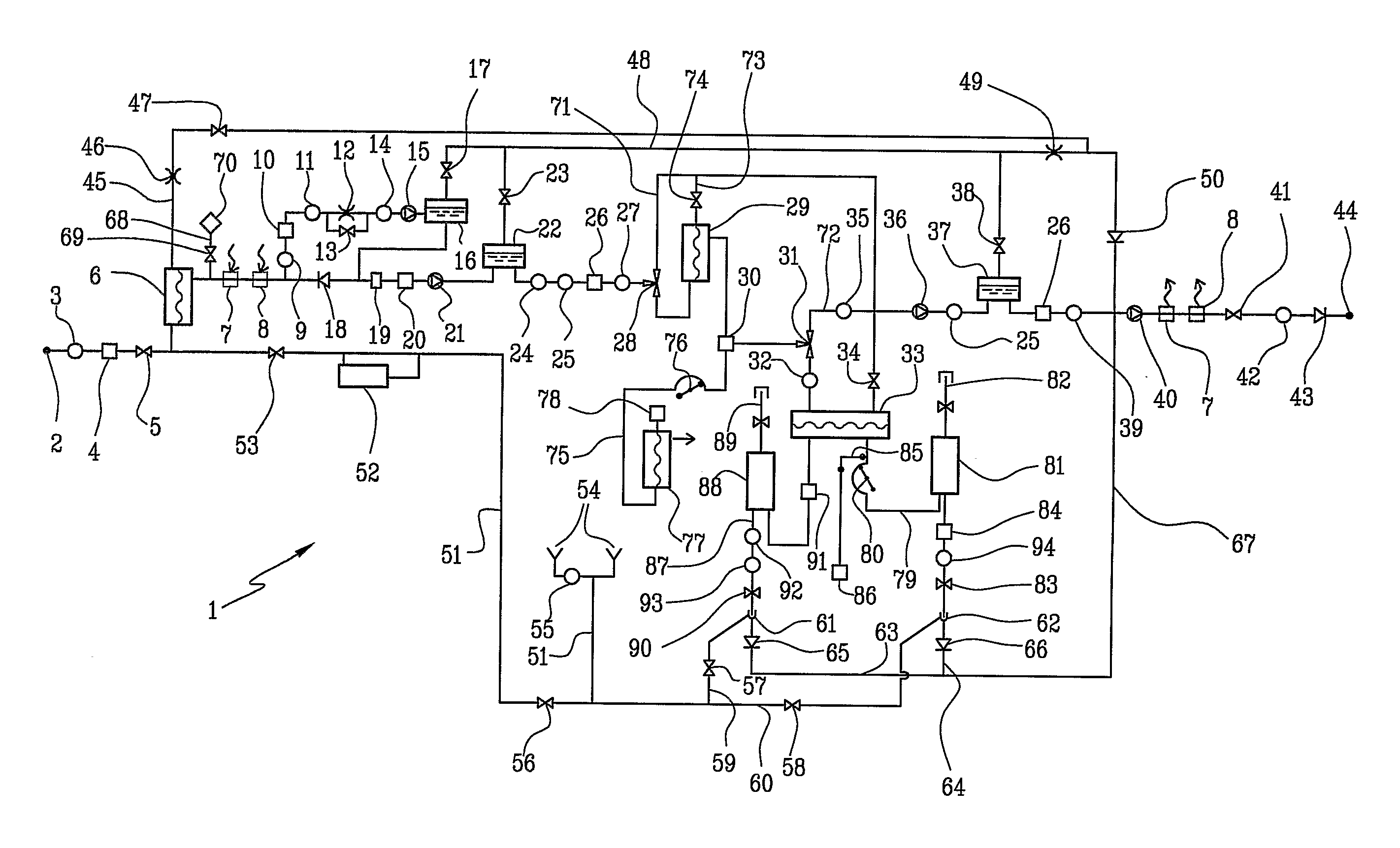
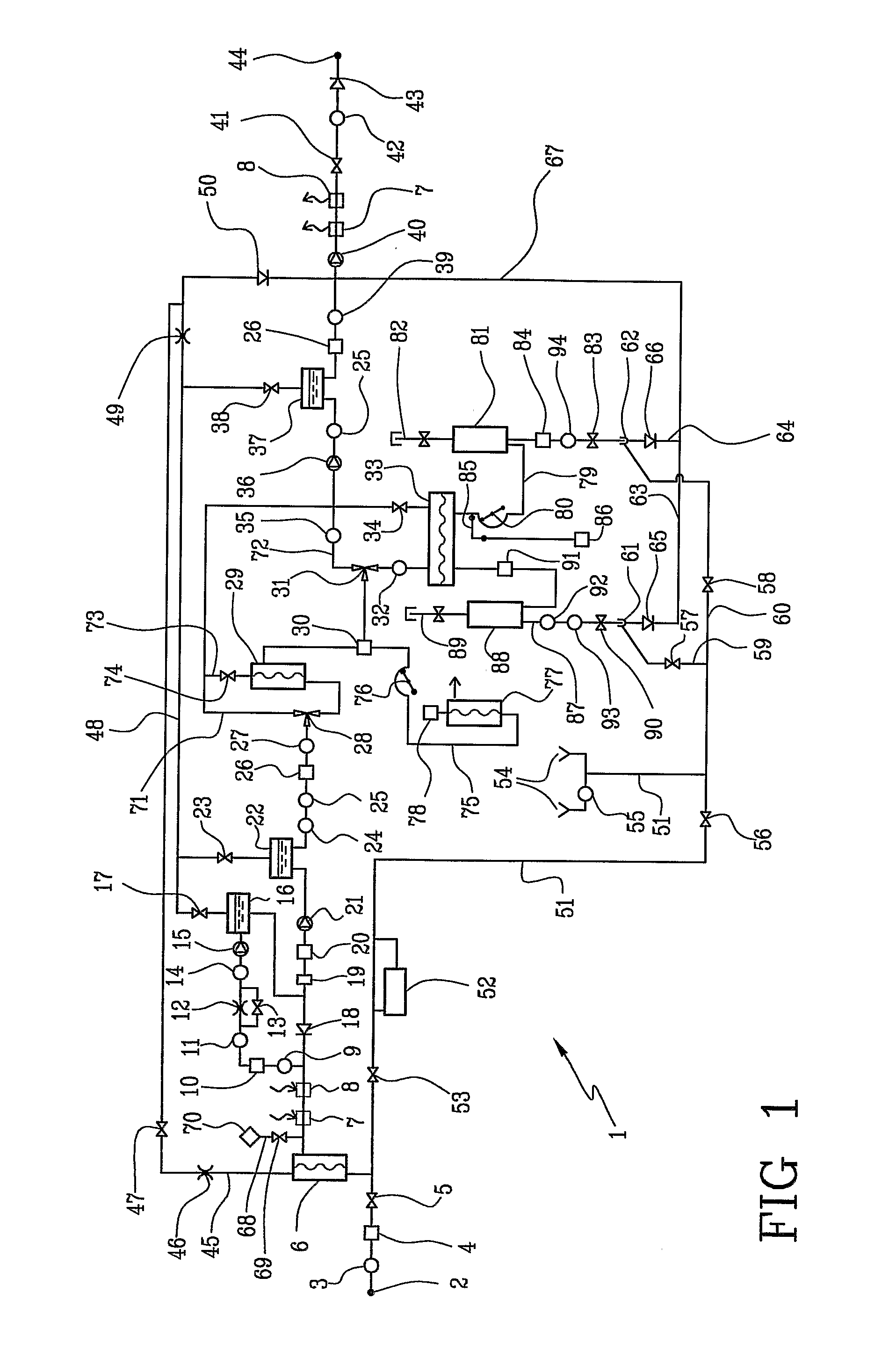
[0023]With reference to FIG. 1, 1 denotes in its entirety a hemodiafiltration apparatus, 2 an inlet end connected to a water source, 3 a pressure sensor at the inlet, 4 an inlet pressure regulator, 5 an on-off valve at the inlet, 6 an ultrafilter for the water at the inlet, 7 a first heat exchanger, 8 a second heat exchanger, 9 a flow sensor or a sensor of the presence of a flow (or a flow switch) at the inlet of the heating and degassing circuit, 10 a heater, 11 a temperature sensor in the heating and degassing circuit, 12 a degassing choke or restrictor, 13 a bypass valve of the degassing choke or restrictor, 14 a pressure sensor for controlling the degassing pump, 15 a degassing pump, 16 a first gas-liquid separator in the heating and degassing circuit, 17 a first degassing valve connected to the vent of the first gas-liquid separator, 18 a check or non-return valve for the heating and degassing circuit, 19 a pressure regulator at the outlet of the heating and degassing circuit, ...


PUM


Abstract

A method and apparatus for priming an extracorporeal blood circuit, in which the patient end of an arterial line (79) is connected to a first discharge port (61), and the patient end of a venous line (87) is connected to a second discharge port (62). The two discharge ports are connected to a used dialysate line which connects a dialyser (33) to a drain. The arterial and venous lines are filled with a priming fluid, while the air contained in the arterial and venous lines is evacuated partly through the first discharge port and partly through the second discharge port. Two check valves (65, 66) prevent flow from the used dialysate line towards the two discharge ports. The invention reduces the risk of errors on the part of an operator readying the priming configuration, as well as the risk of contamination of the extracorporeal circuit during the priming phase.

Description

BACKGROUND OF THE INVENTION[0001]The invention relates to a method and an apparatus for priming an extracorporeal blood circuit.[0002]Specifically, though not exclusively, the invention is usefully applied for priming a dialysis set.[0003]U.S. Pat. No. 4,707,335 describes a system for disinfection and re-use of a membrane separator for blood treatment and fluid transport lines associated to the separator. The system comprises a manifold defining internally a cavity and externally two connectors connected to the patient end of an arterial blood line and a venous blood line, so that the blood lines are intercommunicating with each other, forming a closed fluid circuit in which a disinfecting solution can be made to circulate, for reuse purposes.[0004]U.S. Pat. No. 5,948,251 describes a dialysis machine provided with a disinfection port, a discharge port and a blood pump. Also described is a process for disinfecting a blood tubing set which includes connecting an end of the blood tubin...

Claims


Application Information

Patent Timeline
Patent Type & Authority Applications(United States)
IPC IPC(8): A61M1/16
CPCA61M1/1656A61M1/365A61M1/169A61M1/3626A61M1/3643A61M2205/3331A61M2205/6018A61M2205/6072A61M1/3621A61M1/1627A61M1/1662A61M1/1682A61M1/302A61M1/303A61M1/3465A61M1/3629A61M1/3649A61M1/1686A61M1/30A61M1/309A61M1/3644A61M1/3646A61M1/3647A61M1/1664
Inventor FAVA, MASSIMOSUFFRITTI, MAUROSCAGLIONE, ALESSANDRO
Owner GAMBRO LUNDIA AB
Why Eureka
Try Eureka