Integrated cryosurgical system with refrigerant and electrical power source

Active Publication Date: 2012-10-18
PACIRA CRYOTECH INC
View PDF1 Cites 22 Cited by
  • Summary
  • Abstract
  • Description
  • Claims
  • Application Information

AI Technical Summary

Benefits of technology

[0016]In still another aspect of the present invention, a system for cooling a target tissue in a single patient comprises a probe having a proximal portion, a distal target tissue engaging portion, and a cooling fluid supply lumen therebetween. The probe is insertable distally into the target tissue and a cooling fluid source contains a quantity of cooling fluid. A heater element is thermally engaged with the cooling fluid source and a disposable or rechargeable battery is adapted to provide power to the heater element so as to heat the cooling fluid. The power source has sufficient power to heat the coolin

Problems solved by technology

The power source has sufficient power to heat the refrigerant to a desired temperature and the power source has insufficient power to

Method used


Image

  • Integrated cryosurgical system with refrigerant and electrical power source
  • Integrated cryosurgical system with refrigerant and electrical power source
  • Integrated cryosurgical system with refrigerant and electrical power source

Examples


experiment 1

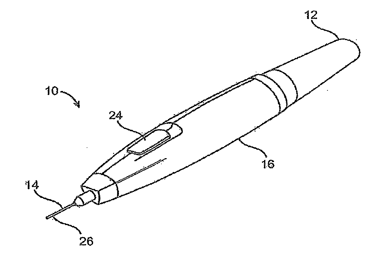
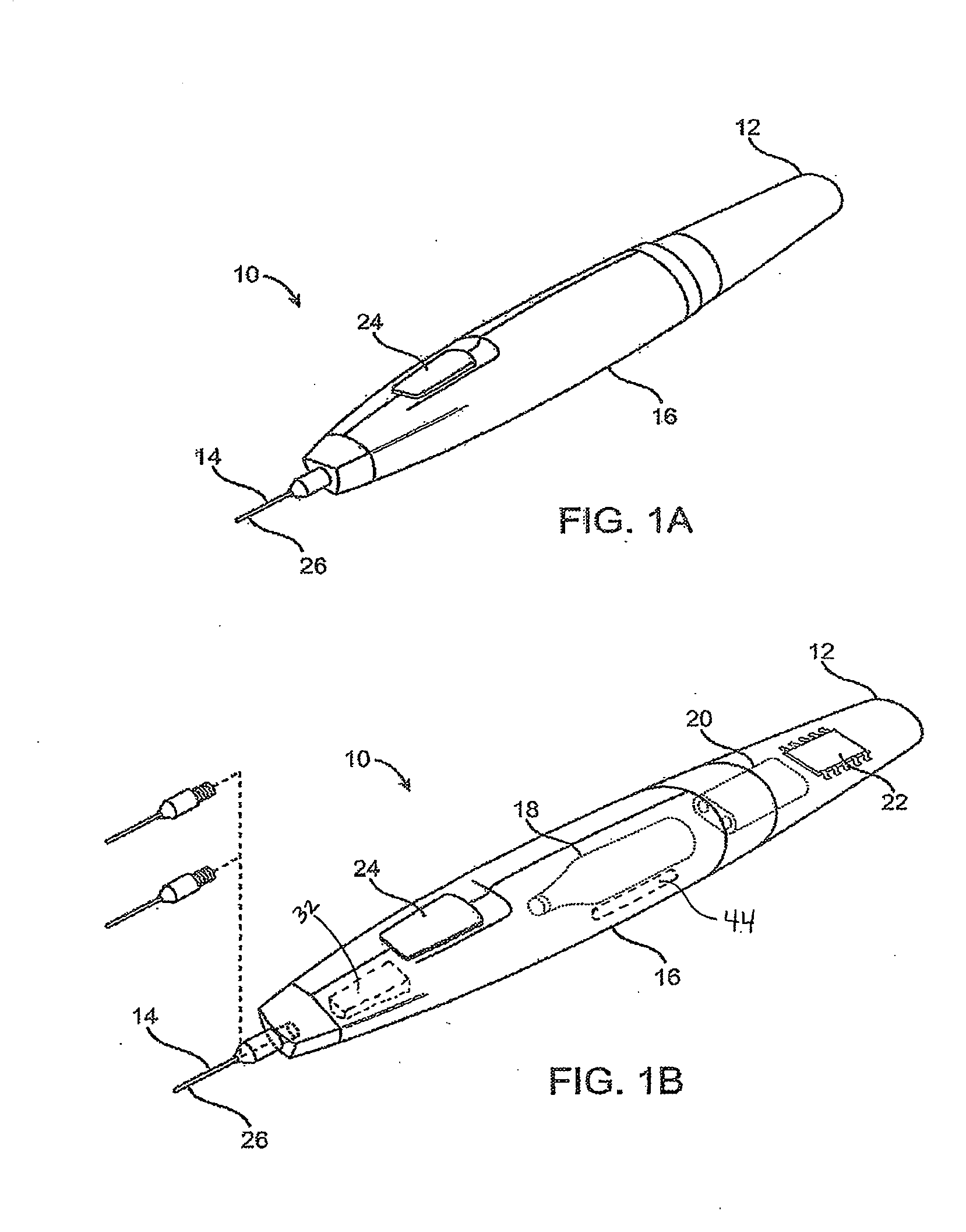
[0042] Testing of the system illustrated in FIG. 1 helps determine upper limits to battery capacity. For example, a system having a 4.8 volt 350 mAh nickel metal hydride battery was used to heat an 8 gram nitrous oxide canister with a 4Ω resistive heater element and a manual valve. The battery was fully charged and allowed to continuously heat the canister for 1050 seconds until depleted. Canister temperature was monitored and it reached a maximum of 81° C. without canister rupture. Therefore, it is apparent that a 4.8 volt 350 mAh battery has insufficient capacity to heat and burst an 8 gram nitrous oxide canister and furthermore, 81° C. is not hot enough to burst this type of canister.

experiment 2

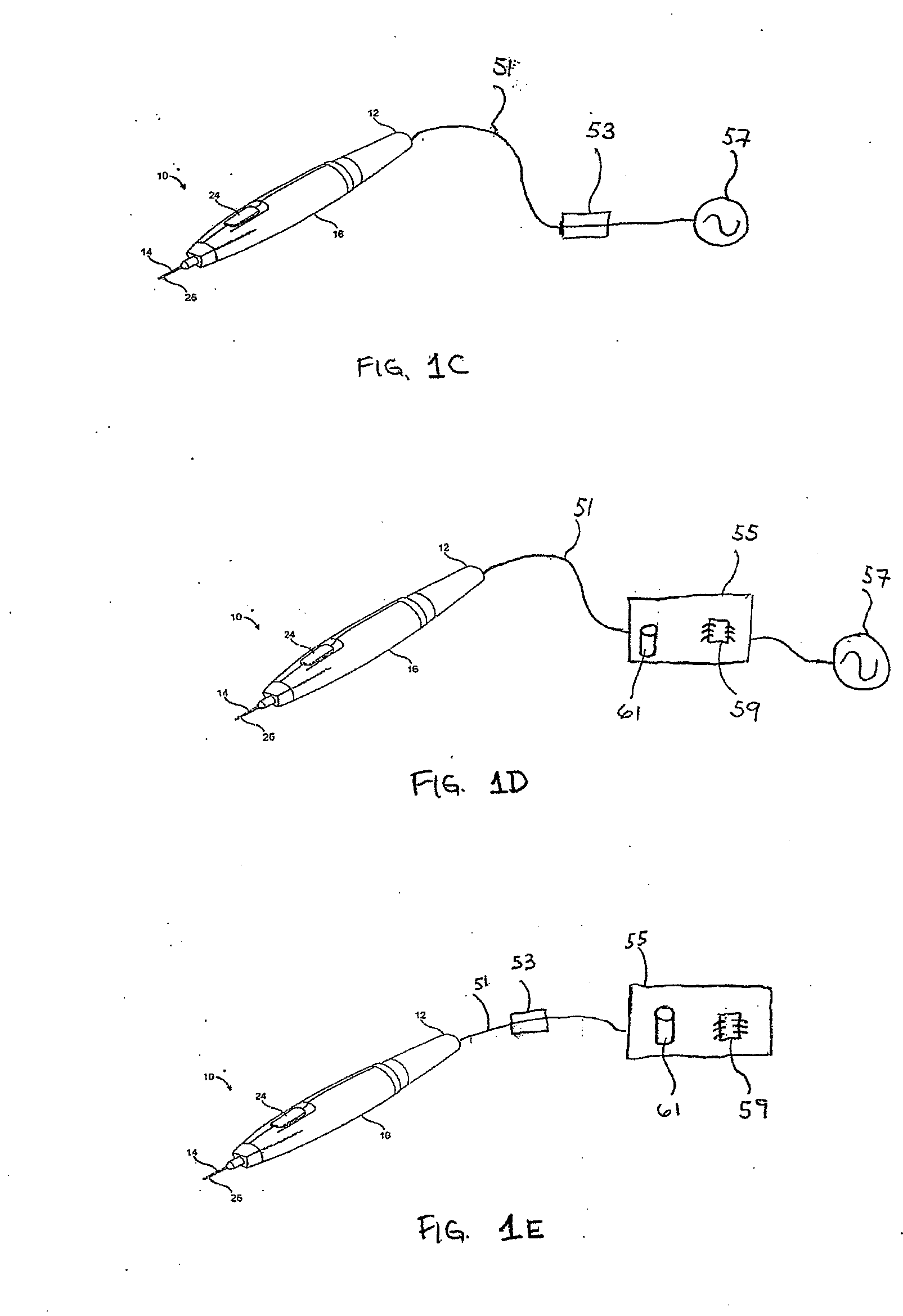
[0043] A 10 volt DC power supply was substituted for the battery described above in Experiment 1. Power was continuously supplied to the canister and temperature was monitored until the canister ruptured. A first canister ruptured at 161° C. and a second canister ruptured at 138° C. The second canister ruptured after 1250 seconds of heating. Therefore, the canister should not be heated above approximately 138° C. and more preferably less than a lower temperature in order to allow for some margin of safety. A larger sample size (here, n=2) is required in order to obtain a statistically significant burst temperature. Furthermore, the burst temperature may vary depending on manufacturing lot of the canister as well as based on the manufacturer. An upper burst temperature limit could be determined by testing a statistically significant number of canisters and factoring in a safety margin. In an exemplary method, the cylinder would not be heated to within 80% of its burst temperature.

[00...


PUM


Abstract

A system for treating tissue in a patient includes a body having a cooling fluid supply path and a tissue piercing probe in fluid communication with the cooling fluid supply path. The probe extends distally from the body and is insertable into the tissue through the patient's skin. A cooling fluid source is fluidly coupled with the probe such that when cooling is initiated, cooling fluid flows in the probe thereby cooling the probe and any adjacent tissue. A heater element is in thermal engagement with the cooling fluid source and a power source provides power to the heater element thereby heating the cooling fluid. The power source has sufficient power to heat the cooling fluid to at least a desired temperature but has insufficient power to heat the cooling fluid above a critical temperature which results in rupture of the cooling fluid source.

Description

BACKGROUND OF THE INVENTION[0001]The present invention is generally directed to medical devices, systems, and methods, particularly for cooling-induced remodeling of tissues. Embodiments of the invention include devices, systems, and methods for applying cryogenic cooling to dermatological tissues so as to selectively remodel one or more target tissues along and / or below an exposed surface of the skin. Embodiments may be employed for a variety of cosmetic conditions, optionally by inhibiting undesirable and / or unsightly effects on the skin (such as lines, wrinkles, or cellulite dimples) or on other surrounding tissue. Other embodiments may find use for a wide range of medical indications. The remodeling of the target tissue may achieve a desired change in its behavior or composition.[0002]The desire to reshape various features of the human body to either correct a deformity or merely to enhance one's appearance is common. This is evidenced by the growing volume of cosmetic surgery p...

Claims


Application Information

Patent Timeline
IPC IPC(8): A61F7/12A61F7/00
CPCA61B18/02A61B2018/00041A61F2007/0056A61B2018/0293A61F2007/0052A61B2018/0281A61B17/34A61F7/12A61M5/158
Inventor FOURKAS, MICHAELWILLIAMS, RONALDGOVENJI, PUNITREYNOLDS, BYRON
Owner PACIRA CRYOTECH INC
Why Eureka
Try Eureka