Coolant Flow Channel Arrangement for a Fluid Cooled Electric Motor

a technology of fluid cooling and flow channel, which is applied in the direction of dynamo-electric machines, supports/encloses/casings, magnetic circuit shapes/forms/constructions, etc., can solve the problems of uneven cooling and lack of adequate heat transfer to the cooling medium, and achieve enhanced thermal conductivity and sealing

Inactive Publication Date: 2012-10-25
KOLLMORGEN CORP
View PDF3 Cites 8 Cited by
  • Summary
  • Abstract
  • Description
  • Claims
  • Application Information

AI Technical Summary

Benefits of technology

[0017]In order to enhance thermal conductivity between the stator plates and the coolant, as well as to enhance sealing to permit use of water as a coolant, the outside dia

Problems solved by technology

The prior art approaches to electric motor cooling have a number of disadvantages, including lack of adequate heat transfer to the cooling medium (typically an oil coolant) due to relatively short exposure of the cooling oil to the stator along relatively short one-pass axial flow paths, an

Method used


Image

  • Coolant Flow Channel Arrangement for a Fluid Cooled Electric Motor
  • Coolant Flow Channel Arrangement for a Fluid Cooled Electric Motor
  • Coolant Flow Channel Arrangement for a Fluid Cooled Electric Motor

Examples


Embodiment Construction

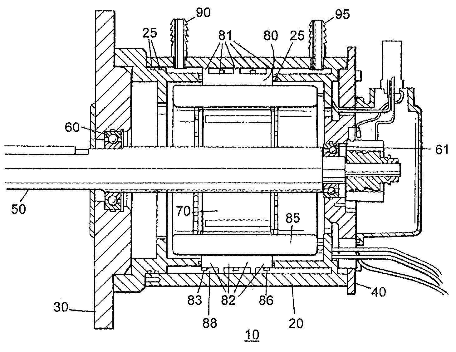
[0022]FIG. 1 is across-section view of an electric motor cooled by a coolant medium in accordance with an embodiment of the present invention. The electric motor 10 has a motor housing 20 and housing end covers 30, 40. A motor shaft 50 is rotatably mounted in bearings 60, 61. A motor rotor 70 is located in a non-rotating manner on motor shaft 50, and rotates with the motor shaft 50 concentrically within a stator 80. The stator 80 includes axial slots in which stator windings 85 are located. The stator windings and the windings of the rotor are electrically connected to external power wires in a conventional manner, not discussed further herein. The motor housing includes a coolant inlet port 90 and a coolant outlet port 95, discussed further, below. The electric motor 10 includes several o-rings 25 for sealing the coolant passages in the assembled electric motor against coolant leakage between the motor components.

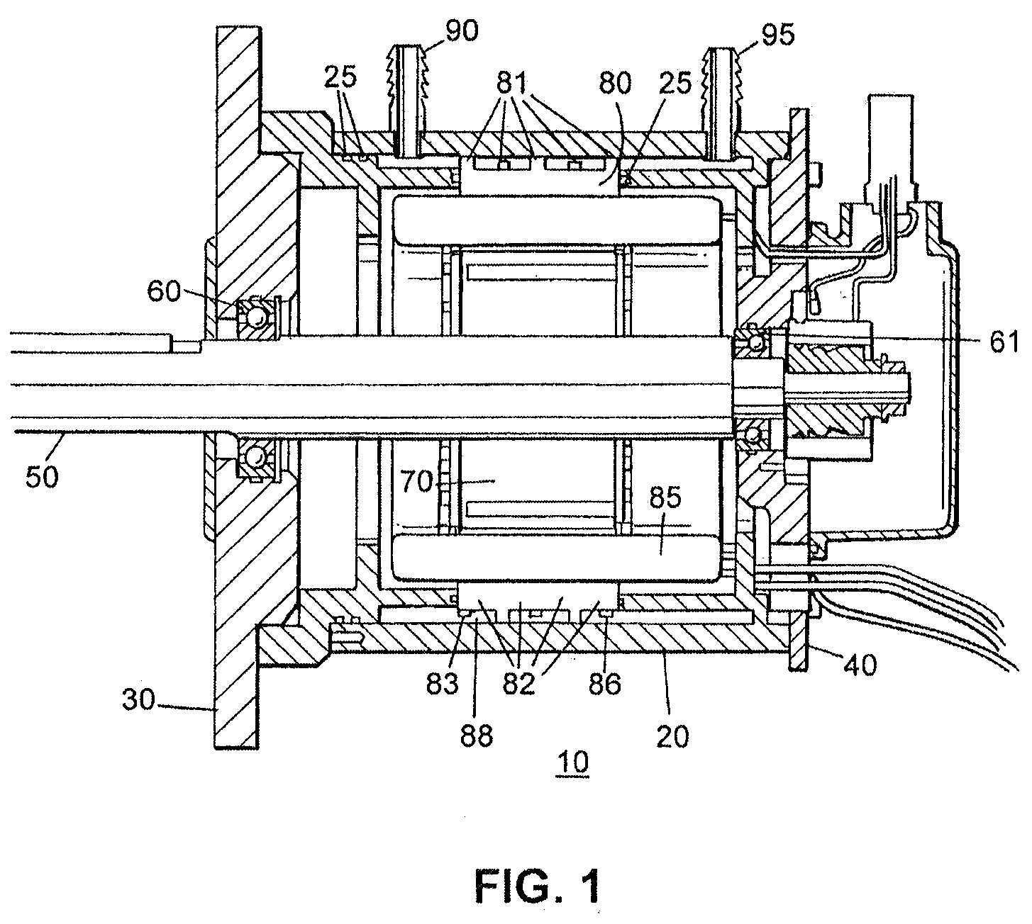
[0023]FIG. 2 is an oblique view of the stator 80 illustrated in FIG. ...


PUM


Abstract

An improved fluid cooling arrangement for an electric machine, such as an electric motor, a generator, or a motor/generator assembly, is provided. In its most general sense, the fluid-cooled electric machine includes a rotor disposed on a motor shaft, a stator surrounding the rotor, and a motor housing surrounding the stator, with the stator formed of a laminated stack of stator plates that is plated at its outer surface.

Description

CROSS-REFERENCE TO RELATED APPLICATIONS[0001]This is a non-provisional application claiming priority to U.S. provisional application Ser. No. 61 / 477,989, filed Apr. 21, 2011, the entire disclosure of which is expressly incorporated by reference herein.BACKGROUND OF THE INVENTION[0002]1. Field of the Invention[0003]The present invention concerns an improved fluid cooling arrangement for an electric motor, generator, or motor / generator assembly. Such assemblies have numerous applications in a variety of fields, and are particularly useful in hybrid vehicle market applications. Use of the invention could occur, for example, in trucks, military vehicles, off-road vehicles, or other automotive vehicles.[0004]2. Description of Related Art[0005]Use of liquid cooling to remove heat from electric motors has been known. For example, U.S. Pat. No. 5,331,238 to Johnsen discloses an electric motor with a stator having three axial cooling channels between an outer circumference of the stator and ...

Claims


Application Information

Patent Timeline
IPC IPC(8): H02K9/19
CPCH02K1/20H02K9/19H02K5/20H02K5/203
Inventor FILIP, ETHANDILLON, KENFIELDS, STEPHEN MARK
Owner KOLLMORGEN CORP
Why Eureka
Try Eureka