Accumulator tank with partition walls

a technology of accumulation tank and partition wall, which is applied in the field of accumulation tank, can solve the problems of reducing the maximum temperature, turbulence in the tank, and destroying stratification, and achieve the effect of efficient accumulation of heat in the tank

Inactive Publication Date: 2012-11-01
FUELTECH SWEDEN
View PDF14 Cites 15 Cited by
  • Summary
  • Abstract
  • Description
  • Claims
  • Application Information

AI Technical Summary

Benefits of technology

[0007]An object of the present invention is to solve the above problems wholly or partly and achieve an improved accumulator tank for handling a heat transfer medium by...

Problems solved by technology

As water is drawn from the heater new water is introduced under pressure from below and this normally creates turbulence in the tank.
When water is drawn after stratification has occurred and new, cold water is supplied from below turbulence is created and the stratification is destroyed.
The mixing of water reduces the maximum temperature and results in inefficient heating.
A problem with this type of tank arises when there is more than one heat source.
If the different heat sources used are, for example, a heat pump and a burner/wood boiler/pellet boiler/oil boiler where, for instance, the temperature of the outlet water from the heat pump is significantly lower than th...

Method used


Image

  • Accumulator tank with partition walls
  • Accumulator tank with partition walls
  • Accumulator tank with partition walls

Examples


Embodiment Construction

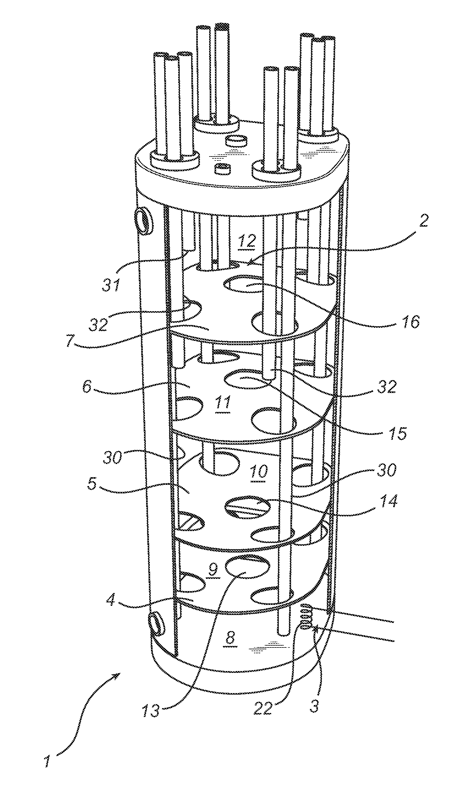
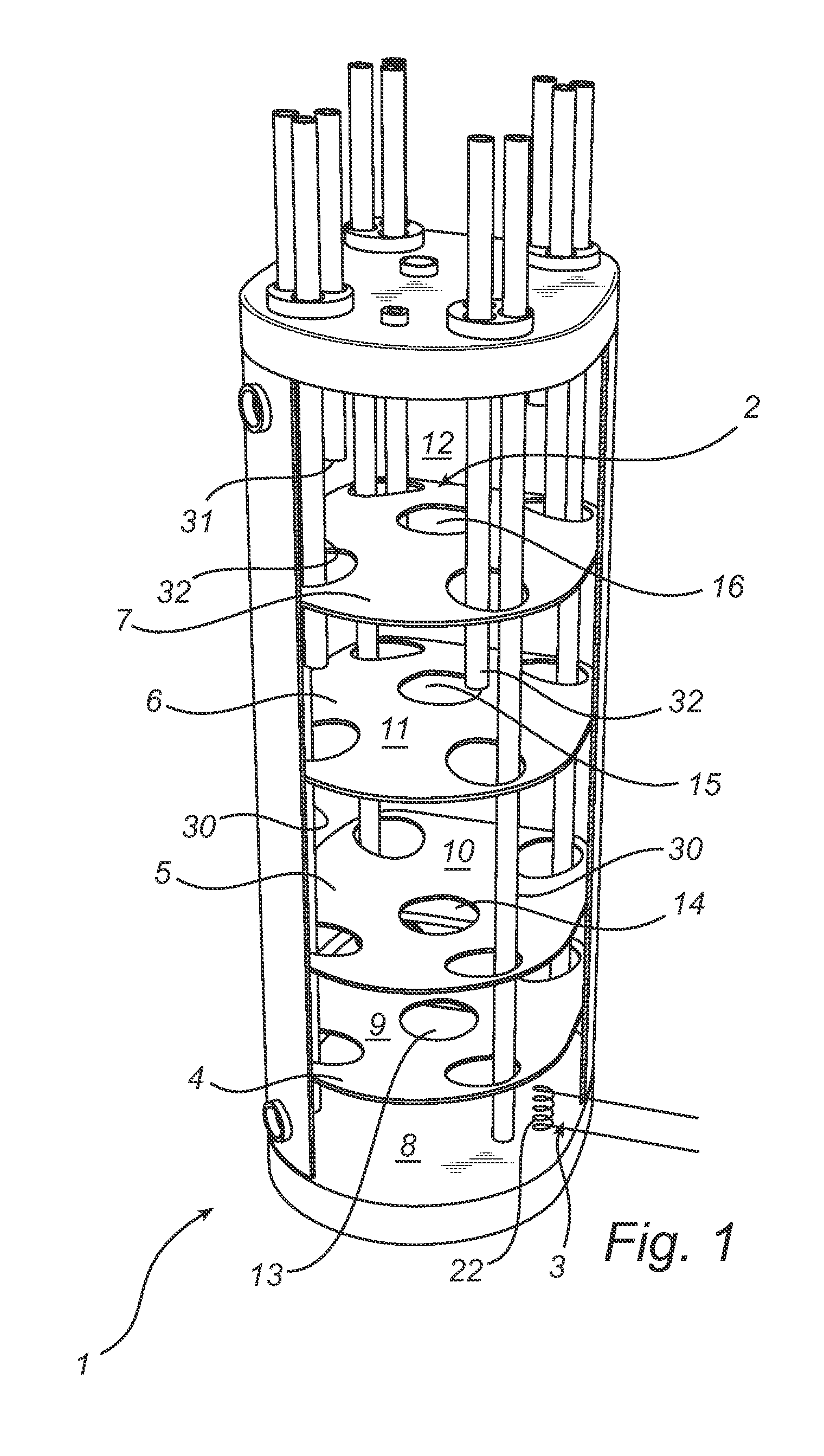
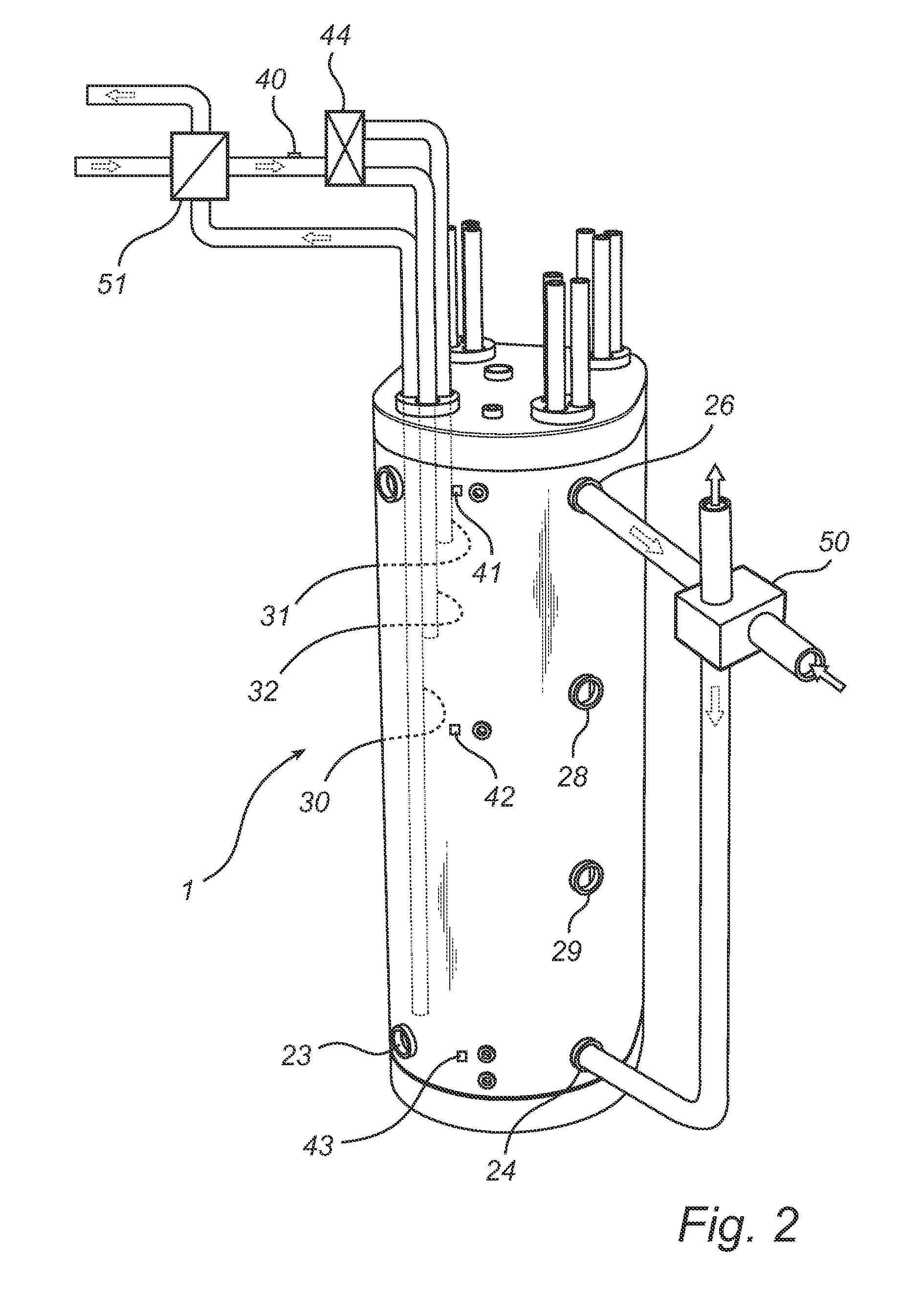
[0026]FIG. 1 shows a preferred embodiment of an accumulator tank 1 according to the present invention. The accumulator tank 1 is upright, shaped like a straight cylinder and has a top section 2 and a bottom section 3 as well as inner partition walls 4, 5, 6, 7 which divide the tank into a plurality of spaces 8, 9, 10, 11, 12. Each partition wall has holes 13, 14, 15, 16 for allowing communication of medium between the spaces 8, 9, 10, 11, 12. There is also provided in each partition wall and in the upper end surface of the accumulator tank 1 holes 17, 18, 19, 20 through which pipes or bundles of pipes 21 are adapted to extend. In the circumferential surface of the accumulator tank 1, two or more connecting means 23, 24, 26, 27, 28, 29 are provided for communication with two or more spaces 8, 9, 10, 11, 12 of the accumulator tank 1.

[0027]A connection can be established with each of the spaces 8, 9, 10, 11, 12 according to the embodiment shown in FIG. 1 via the respective penetrating ...


PUM


Abstract

An accumulator tank for handling a heat transfer medium, is disclosed having a tank top section and a bottom section. The accumulator tank is connected to at least one heat emitting system and at least one heat-absorbing system. The accumulator tank has a plurality of partition walls located inside the tank and arranged between the bottom section and the top section for the purpose of dividing the tank into a plurality of spaces. The systems being each connected to at least one respective space so that a temperature gradient is created between the bottom section and the top section. Also disclosed is a system for distributing and handling heat and/or cold, including the accumulator tank.

Description

TECHNICAL FIELD[0001]The invention relates to an accumulator tank for handling a heat transfer medium, comprising a tank with a top section and a bottom section, wherein said accumulator tank is connected to at least one heat-emitting system and at least one heat-absorbing system. The invention further concerns a system for distributing and handling heat and / or cold, comprising an accumulator tank as described above.BACKGROUND ART[0002]When distributing and handling heat, hot water and / or cold in a house, a vehicle, a machine or an industrial plant an accumulator tank for storing hot or cold medium is provided in most cases. In a heating system for a house the accumulator tank is normally a hot-water heater with an integrated electric heater. Several other heating systems are often connected to said system, such as a heat pump, solar heat or a pellet boiler. In vehicles such as cars, lorries or boats the cooling water of the motor and / or a burner / heater is / are often used to heat the...

Claims


Application Information

Patent Timeline
IPC IPC(8): F24H9/14F24H1/18F24D11/00F24H9/13
CPCF24D11/002F24H9/124F28D20/0039Y02E60/142F28D2020/0078F28D2020/0086F28D2020/006F24D2220/08F24H1/202F24H9/0005F24H9/14Y02E60/14F24H9/133F15B1/26F24D11/00F24H1/00F24H1/18F28D20/00F28D20/02F24H1/181
Inventor JONSSON, MIKAEL
Owner FUELTECH SWEDEN
Why Eureka
Try Eureka