Method for separating grinding oil from grinding slurry; separating station for carrying out said method and plant according to said method

a technology of grinding oil and slurry, which is applied in the direction of gravity filter, sediment separation, loose filtering material filter, etc., to achieve the effect of reducing the thickness of the layer, reducing the amount of slurry, and good heat utilization

Inactive Publication Date: 2012-11-01
ERWIN JUNKER MASCHNINENFAB
View PDF25 Cites 2 Cited by
  • Summary
  • Abstract
  • Description
  • Claims
  • Application Information

AI Technical Summary

Benefits of technology

[0005]The advantageous effects of the method according to the invention come about firstly by the grinding slurry being spread out on a carrier into a flat layer of low height. exposing the free surface of the flat layer of grinding slurry to the effective range of an inductor plate acting from above provides clear geometrical conditions for the heating up of the layer. Since the heating takes place from above, the grinding oil that is reduced in its viscosity can leave the grinding slurry in a downward direction, because suitable openings are provided in the carrier. The grinding slurry heated up still further is consequently freed immediately of the grinding oil components that have become mobile and is well able to undergo further heating. The removal of the grinding slurry reduced in its grinding oil content takes place outside the effective range of the inductor plate, whereas the application of the layer of grinding slurry to the carrier may take place either in or outside its effective range. This arrangement ensures good utilization of the heat generated by the inductor plate, which is produced directly in the metal components of the grinding slurry. The spreading out and heating of a pizza dough may serve as a graphic analogy for the approach according to the invention. If the grinding slurry is to be applied to the carrier in the effective range of the inductor plate, this may take place for example from the side obliquely downward onto the carrier, into the intermediate space between the inductor plate and the carrier.
[0006]Particularly good experiences have been had with a layer of grinding slurry 2 to 30 mm thick on the carrier. However, this size range is in any case not obligatory; depending on the characteristics of the grinding slurry and the degree of kinematic viscosity of the grinding oil, advantageous results can also be achieved with greater layer thicknesses.
[0007]The inductive heating of the grinding slurry is of course dependent on how pronounced the ferromagnetic properties of the metal chips and / or the metal dust in the grinding slurry are. The increase in temperature may take place to differing degrees, by the induction heating being switched on with differing degrees of intensity and duration. When there are weaker ferromagnetic properties, it is expedient to place onto the free surface of the flat layer of grinding slurry a steel plate, which is located in the effective range of the inductor plate between the latter and the free surface of the layer of grinding slurry. In this case, the inductor plate especially heats up the steel plate, which then gives off its heat to the layer of grinding slurry lying thereunder.
[0008]In particular if the grinding slurry is still contaminated by further substances, it may also be expedient to place in the flat layer of grinding slurry a further steel plate, which is then located at a distance above the carrier, that is to say is arranged within the layer of grinding slurry. This additional plate may be formed as a perforated plate or as a screen and is likewise inductively heated by the inductor plate. This heat source located within the layer of grinding slurry allows the disadvantages of weaker ferromagnetic properties or of contamination of the grinding slurry to be balanced out.
[0009]In a first refinement, the method according to the invention may be performed by divided portions of the grinding slurry being spread out on a carrier bowl, which is then brought into the effective range of the inductor plate from below. This leads to a comparatively simple plant that is suitable for separating not excessively great amounts of the grinding slurry.
[0010]Another procedure involves forming the carrier as an endless conveyor on which there are formed at least three carrier bowls, which are fed one after the other to the operations of a) spreading, b) inductively heating by the inductor plate and c) unloading. The movement of the endless conveyor in this case takes place cyclically, and for the heating operation the inductor plate is respectively lowered from above onto the carrier bowl concerned. The endless conveyor may in this case be formed as a belt conveyor with a linear conveying direction or else as a circular conveyor. Further advantageous refinements are specified in dependent claims relating to the individual methods.

Problems solved by technology

However, this size range is in any case not obligatory; depending on the characteristics of the grinding slurry and the degree of kinematic viscosity of the grinding oil, advantageous results can also be achieved with greater layer thicknesses.

Method used


Image

  • Method for separating grinding oil from grinding slurry; separating station for carrying out said method and plant according to said method
  • Method for separating grinding oil from grinding slurry; separating station for carrying out said method and plant according to said method
  • Method for separating grinding oil from grinding slurry; separating station for carrying out said method and plant according to said method

Examples


first embodiment

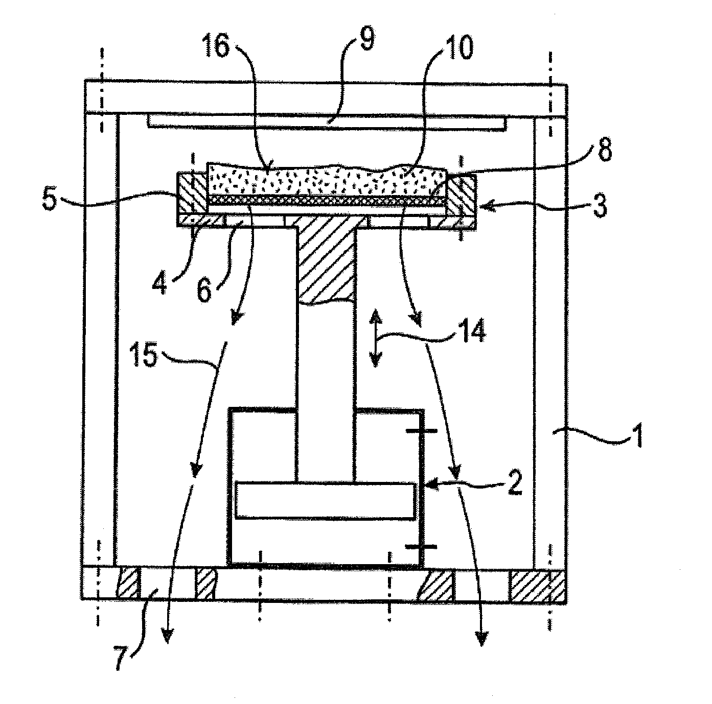
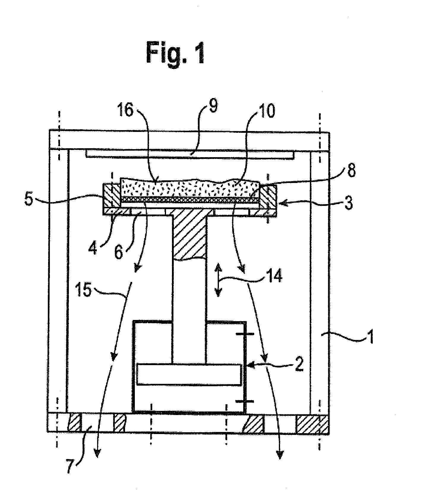
[0025]In FIG. 1, a separating station is represented. Arranged here in a frame 1 is a lifting device 2, which is indicated in the form of an adjusting piston with a solid piston rod that is suitable as a supporting column. The lifting device serves the purpose of moving a carrier bowl 3 upward and downward, cf. the directional arrow 14 for the lifting movement. The carrier bowl comprises a flat plate 4 with a rising-up rim 5, surrounding the flat plate 4, and has a circular cross section. The flat plate 14 is provided with openings 6, through which separated grinding oil can flow off, cf. the directional arrow 15 for the flow-off direction. The base of the frame 1 is also provided with openings 7 for the same purpose.

[0026]Arranged at a distance above the flat plate 4 of the carrier bowl 3 is a permeable intermediate base 8. It may be formed as a screen base or in the form of a perforated plate. The through-flow openings of the intermediate base 8 are small in relation to the openi...

third embodiment

[0049]In the case of the third embodiment according to FIGS. 6 and 7, the endless conveyor is formed as a circular conveyor 51. In FIG. 6, which corresponds to a section B-B through FIG. 7, the principle is only shown schematically. The circular conveyor 51 has the form of a flat circular disk that is rotatable about its center axis 63, that is to say forms a carousel. The direction of rotation of the circular conveyor 51 is identified by the directional arrow 52. On the circular conveyor 51 there are three circular carrier bowls 53 for receiving and treating divided layers of grinding slurry 54, cf. FIG. 7. The way in which they operate is the same in principle as in the case of the separating station already described, with the belt conveyor which is moved cyclically in a linear direction. Each of the three carrier bowls 53 passes one after the other through the treatment units of a) loading and spreading, b) inductively heating and c) unloading.

[0050]FIG. 7, which corresponds to ...


PUM

PropertyMeasurementUnit
thicknessaaaaaaaaaa
thickaaaaaaaaaa
temperatureaaaaaaaaaa

Abstract

The invention relates to a plant for separating grinding slurry originating from grinding machines into metal chips and grinding oil. According to the invention, a carrier bowl (3) in a frame (1) is filled with a divided volume of the grinding slurry (10). The carrier bowl (3) has a perforated plate (4) having an edge (5) as a floor and a sieve-like intermediate floor (8). By means of a lifting device (2), the carrier bowl (3) is moved to the effective region of an inductor plate (9) serving as a heater. The induction heat heats the ferromagnetic steel or iron particles present in the grinding slurry (10). Said heating effects a reduction in viscosity of the grinding oil in the grinding slurry (10), from which substantial portions flow downward through the openings (6) or (7). In certain cases, the effect can be improved by placing a steel plate on the free surface (16) of the grinding slurry layer (10).

Description

BACKGROUND OF THE INVENTION[0001]The invention relates to a method for separating grinding oil from grinding slurries and to separating stations for carrying out the method. A method and a separating station of this type are known from DE 196 00 505 A1.[0002]The known method is already designed for creating the preconditions for disposal or reuse of the individual grinding slurry components. Reducing the content of grinding oil in the grinding slurry to a sufficient extent allows the metal component to be reused in a steelworks or in a foundry, or the grinding oil may be separated with such a degree of purity that it can be reconditioned and reused. The known method pursued the aim of reducing the costs of the separating or purifying method, with low expenditure on equipment and process control. As provided by the proposal of DE 196 00 505 A1, for this purpose a method of mechanical separation is combined with a thermal process. To be specific, according to DE 196 00 505 A1, the mec...

Claims


Application Information

Patent Timeline
Patent Type & Authority Applications(United States)
IPC IPC(8): B01D35/18B01D21/00B01D21/26
CPCB01D29/09B24B57/00B01D29/843B01D29/824
Inventor JUNKER, ERWIN
Owner ERWIN JUNKER MASCHNINENFAB
Why Eureka
Try Eureka