Radiation imaging device

Inactive Publication Date: 2012-11-01
FUJIFILM CORP
View PDF0 Cites 12 Cited by
  • Summary
  • Abstract
  • Description
  • Claims
  • Application Information

AI Technical Summary

Benefits of technology

[0027]According to the present invention, the anisotropic heat transfer plate is disposed between the top plate and the detection panel in the housing. Thus, it is possible to prevent the occurrence of temperature variations in a detection surface of the detection panel caused by heat transferred from the top plate of the housing.
[0028]The anisotropic heat transfer plate made of carbon fibers has high radiation transparency, and can transfer and release the heat from the top plate in an arb

Problems solved by technology

Firstly, the housing must be lightweight enough to enable portability.
Thirdly, the X-ray irradiation surface of the housing must have rigidity enough to endure a load imposed by the patient's body part, because when the electronic cassette detached from the imaging support is used on a bed or a table, the body part to be examined is put on the X-ray irradiation surface of the housing.
When the electric charge accumulated in each pixel of the detection panel is read out by a readout circuit through plural signal lines, the heat sometimes interferes with the operation of the readout circu

Method used


Image

  • Radiation imaging device
  • Radiation imaging device
  • Radiation imaging device

Examples


Embodiment Construction

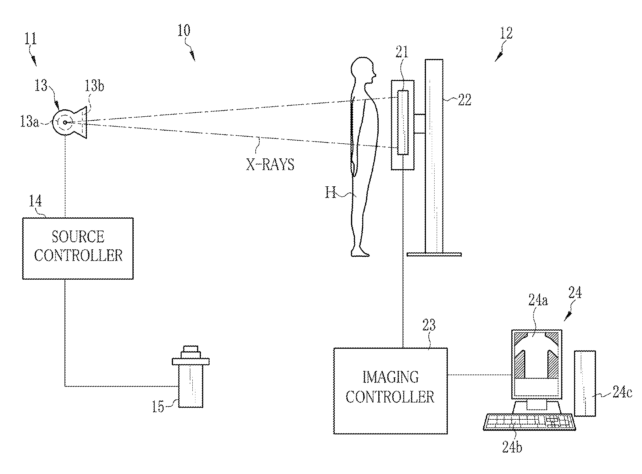
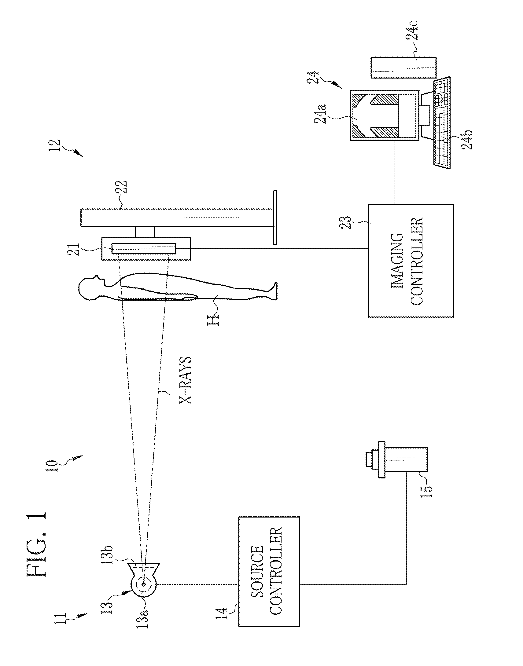
[0039]As shown in FIG. 1, a radiation image capturing system, for example, an X-ray image capturing system 10 is constituted of an X-ray generating apparatus 11 and an X-ray image capturing apparatus 12. The X-ray generating apparatus 11 has an X-ray source 13, a source controller 14 for controlling the X-ray source 13, and an exposure switch 15. The X-ray source 13 has an X-ray tube 13a for emitting X-rays, and a collimator 13b for limiting an irradiation field of the X-rays emitted from the X-ray tube 13a.

[0040]The X-ray tube 13a has a cathode composed of a filament for emitting thermoelectrons, and an anode (target) for radiating the X-rays by collision of the thermoelectrons emitted from the cathode. The collimator 13b is composed of, for example, a plurality of X-ray shielding lead plates disposed along each side of a rectangle so as to form a rectangular irradiation opening in a middle through which the X-rays propagate. Changing the position of the lead plates can vary the s...


PUM


Abstract

An electronic cassette has a top plate, an anisotropic heat transfer plate, a detection panel, and a scintillator disposed in this order from an X-ray irradiation side. The scintillator converts X-rays transmitted through the top plate, the anisotropic heat transfer plate, and the detection panel into visible light. The detection panel performs photoelectric conversion of the visible light. The anisotropic heat transfer plate is composed of a lamination of first prepregs in which all carbon fibers are oriented in a heat flow direction. The top plate is composed of an alternate lamination of the first prepregs and second prepregs that have carbon fibers oriented in a signal line direction. Body heat of a patient is transferred to the top plate, and is transferred in the heat flow direction in the anisotropic heat transfer plate, and then is released from a housing through heat absorbing members.

Description

BACKGROUND OF THE INVENTION[0001]1. Field of the Invention[0002]The present invention relates to a radiation imaging device that converts radiation into visible light and obtains a radiographic image.[0003]2. Description Related to the Prior Art[0004]As a type of medical imaging system using radiation such as X-rays, an X-ray image capturing system is known. The X-ray image capturing system is constituted of an X-ray generating apparatus for applying the X-rays to a patient's body part to be examined, and an X-ray image capturing apparatus for taking an X-ray image of the body part. The X-ray image capturing apparatus has a radiation imaging device that captures a radiographic image as an electric image. A type of radiation imaging device using a FPD (flat panel detector) is recently in practical use. The FPD has a detection surface formed of a matrix of pixels each of which accumulates signal charge by an amount corresponding to an amount of the X-rays incident thereon. In the FPD,...

Claims


Application Information

Patent Timeline
IPC IPC(8): G01T1/20
CPCG01T1/20G01T1/244
Inventor NARIYUKI, FUMITONAKATSUGAWA, HARUYASU
Owner FUJIFILM CORP
Why Eureka
Try Eureka