Virtual machine and application movement over a wide area network

Active Publication Date: 2012-11-01
AVAGO TECH INT SALES PTE LTD
View PDF6 Cites 220 Cited by
  • Summary
  • Abstract
  • Description
  • Claims
  • Application Information

AI Technical Summary

Benefits of technology

[0022]Long distance cloud migration (LDCM) as described here is one embodiment to overcome the limitations faced by the cloud migration techniques over long distance, high speed WAN infrastructures. LDCM is designed to overcome the negative effects of existing TCP/IP mechanisms on the efficient use of available bandwidth. LDCM is also designed to act as an acceleration engine to optimize various hypervisor, stora

Problems solved by technology

This challenge gets more complicated when the migration needs to be done with zero impact on the user and it becomes virtually impossible if the migration has to be performed over long distances.
Huge RTT values influence the congestion control mechanism and cause a very long slow startup phase and hence also result in sub optimal bandwidth usage.
If a congestion event occurs in such a situation, the connection window size will be dropped to zero and the slow start phase is triggered all over again, causing further reduction in the throughput.
1) Window Size: The TCP window size is a 16 bit field advertised in the TCP header which limits the window size to a maximum value of 64 KB. TCP can only send 64 KB before it receives acknowledgement. Since 64 KB takes 0.5 ms to transmit across a 1 Gbps link, even 1 ms latency could cut the TCP performance by a factor four. To maintain the line rate at 1 Gbps with 1 ms of network latency, a window size of 128 KB is needed. Higher network latencies demand bigger window sizes to maintain the same line rate. For example, at 1 Gbps network speed and 60 ms RTT, a receive window size of 8 MB is needed. The application servers cannot handle such high demand on memory since they handle multiple TCP connections. A realistic window size limit is 3 MB, as shown in FIG. 3.
2) Network Reordering: Dynamically load balancing networks cause excessive false congestion events due to reordering done at the receiver. Due to the dynamic load balancing nature of the network, the packets might arrive out of order with some packets undergoing more delay to reach the receiver than the others.

Method used


Image

  • Virtual machine and application movement over a wide area network
  • Virtual machine and application movement over a wide area network
  • Virtual machine and application movement over a wide area network

Examples


Embodiment Construction

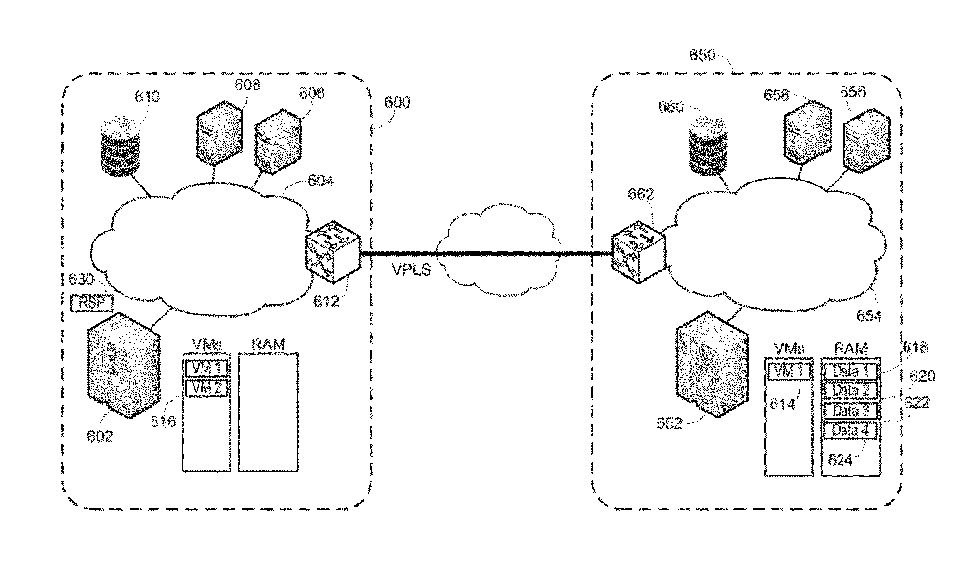
[0043]Referring to FIG. 7, a network illustrating portions according to the present invention is shown. A first data center 700 is shown having three separate internal networks, a TRILL network 702, a normal Ethernet spanning tree protocol (STP) network 704 and a storage area network (SAN) 706. Application servers 708 are connected to the TRILL network 702, while application servers 710 are connected to the STP network 704 and the SAN 706. Storage 712 is shown connected to the SAN 706. Each of the networks 702, 704 and 706 has a converged network extension (CNE) device 714, 716, 718 connected. The CNE devices 714, 716, 718 are connected to a router 720, which in turn is connected to a WAN 722. A second data center 750 is similar, having a VCS Ethernet fabric network 752 and a SAN 754. Application servers 756 are connected to each network 752 and 754, with storage connected to the SAN 754. CNE devices 760, 762 are connected to each network 752, 754 and to a router 764, which is also ...


PUM


Abstract

Long distance cloud migration (LDCM) to overcome the limitations faced by the cloud migration techniques over long distance, high speed WAN infrastructures. LDCM overcomes the negative effects of existing TCP/IP mechanisms on the efficient use of available bandwidth. LDCM also acts as an acceleration engine to optimize various hypervisor, storage and security applications.

Description

CROSS REFERENCE TO RELATED APPLICATIONS[0001]This application claims the benefit under 35 U.S.C. §119(e) of U.S. Provisional Patent Application Ser. No. 61 / 413,442 entitled “LONG DISTANCE CLOUD MIGRATION,” filed Nov. 14, 2010, which is hereby incorporated by reference.BACKGROUND OF THE INVENTION[0002]1. Field of the Invention[0003]The invention relates to virtual machines associated with a computer system and movement of those virtual machines between computer systems separated by a wide area network.[0004]2. Description of the Related Art[0005]Businesses are expected to migrate, consolidate and maintain their data centers without any downtime while providing high availability for applications.[0006]Typical data center organization is shown in FIG. 1. Two data centers 100, 150 are illustrated. Each has a series of application server clusters 102, 152 which execute the actual applications, such as in a SaaS (software as a Service) architecture. Data is stored in a storage fabric 104,...

Claims


Application Information

Patent Timeline
IPC IPC(8): G06F9/455G06F15/16
CPCG06F9/45558G06F2009/4557H04L65/1066G06F9/455H04L47/70G06F9/4856H04L47/15H04L47/193
Inventor NARAYANASAMY, SENTHILKUMARPULLA, INDIRA RADHIKA
Owner AVAGO TECH INT SALES PTE LTD
Why Eureka
Try Eureka