Air conditioning system for vehicle

Inactive Publication Date: 2012-11-08
HONDA MOTOR CO LTD
View PDF3 Cites 17 Cited by
  • Summary
  • Abstract
  • Description
  • Claims
  • Application Information

AI Technical Summary

Benefits of technology

[0007]The present invention has been made in order to solve the aforementioned problems. It is an object of the present invention to provide a vehicular air conditioning system, which is capable of increasing heat exchange efficiency and maintaining good air-conditioning performance as a result of stably circulating a refrigerant by means of a simple and economical arrangement.
[0010]According to the present invention, the gas-liquid separation refrigerant storage unit functions as a buffer for making up or compensating for a refrigerant shortage in a cooling mode. Therefore, when the air conditioning system operates in the heating mode at an increased ambient air temperature, as well as when the air conditioning system operates in a transient mode such as a dehumidifying heating mode, no refrigerant shortage occurs, thereby allowing the air conditioning system to perform air-conditioning in a stable manner.
[0012]It is thus possible to increase heat exchange efficiency and to maintain good air-conditioning performance by stably circulating the refrigerant by means of a simple and economical arrangement.

Problems solved by technology

Therefore, the number of components dedicated to the heating mode is increased, which makes the vehicular air conditioning apparatus uneconomical.
Consequently, air-conditioning performance is lowered due to the refrigerant shortage, resulting in the need for a power increase caused by a capability shortage of the compressor 1, and also resulting in poor mileage on account of the power increase.

Method used


Image

  • Air conditioning system for vehicle
  • Air conditioning system for vehicle
  • Air conditioning system for vehicle

Examples


first embodiment

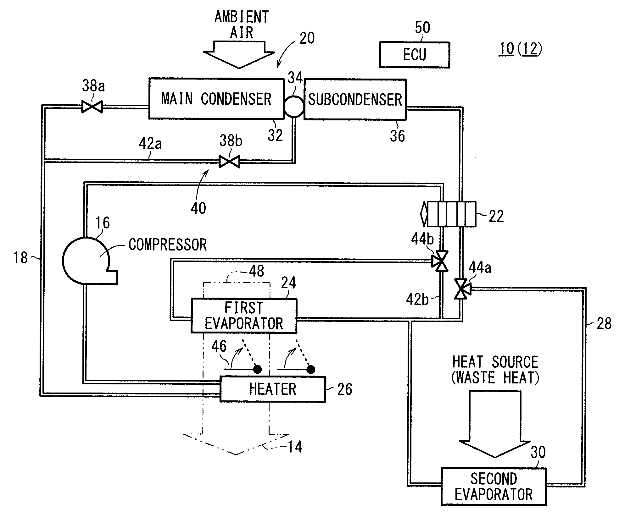
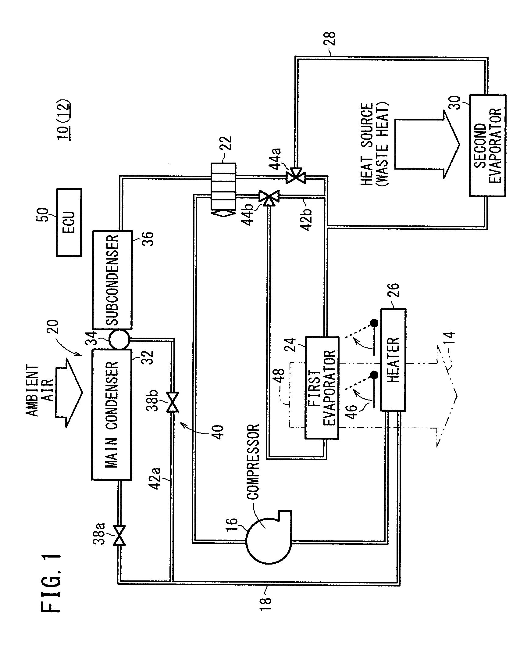
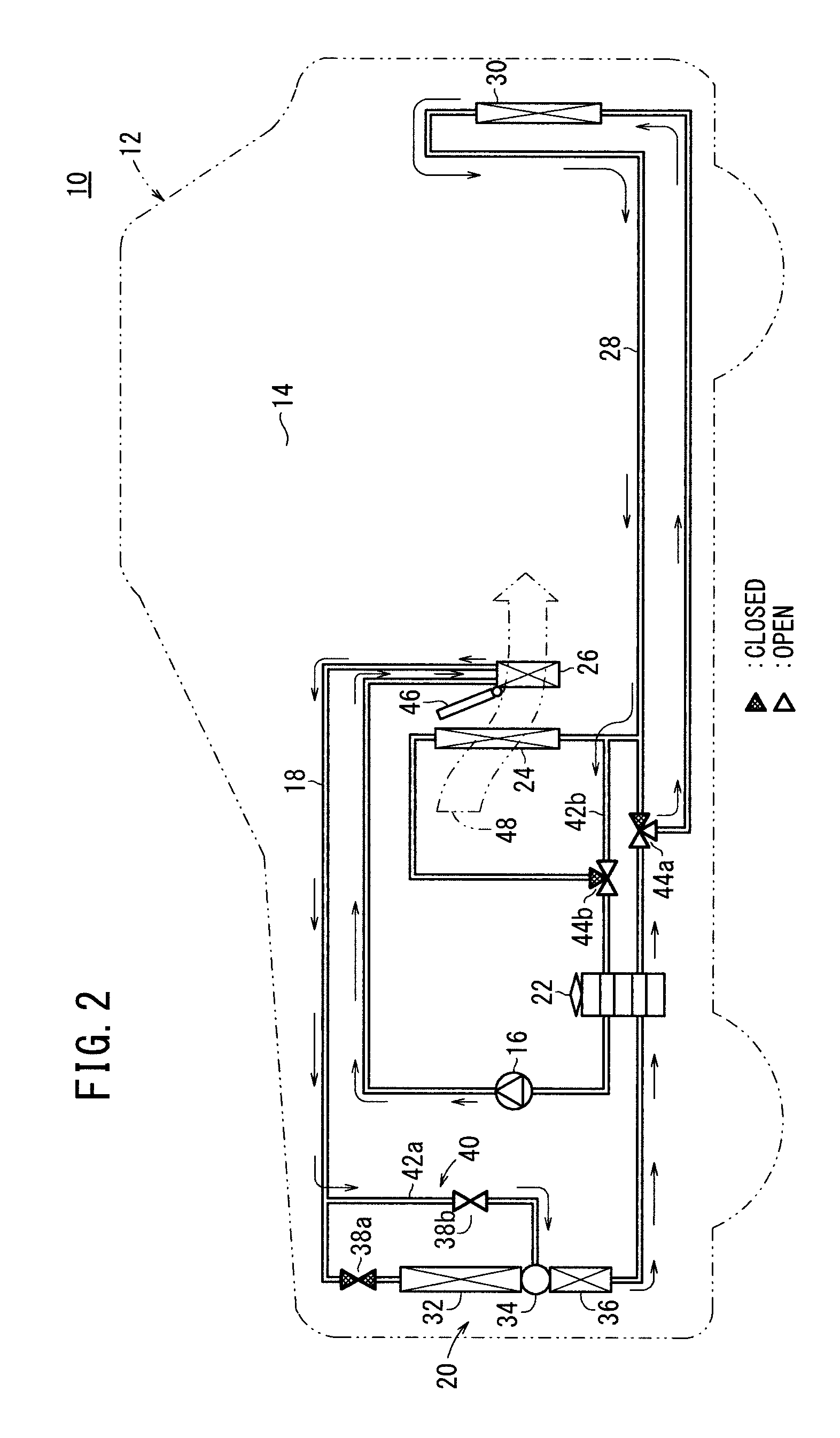
[0032]As shown in FIGS. 1 and 2, a vehicular air conditioning system 10 according to the present invention is incorporated in an automobile (vehicle) 12 for air-conditioning a passenger cabin (vehicle compartment) 14 of the automobile 12.

[0033]The air conditioning system 10 has a heat pump circulation path 18 for circulating a refrigerant via a compressor 16. The heat pump circulation path 18 includes therein a condenser unit (condenser) 20 for performing heat exchange between the refrigerant and ambient air, an expansion valve 22 for depressurizing the refrigerant delivered from the condenser unit 20, a first evaporator (evaporator) for performing heat exchange between the refrigerant that has passed through the expansion valve 22 and air-conditioning air, and a heater 26 for performing heat exchange between the refrigerant delivered from the compressor 16 and the air-conditioning air that has passed through the first evaporator 24.

[0034]The heat pump circulation path 18 branches i...

second embodiment

[0063] as shown in a cycle diagram illustrated in FIG. 7, since the flow rate control valve 64 is used as a pressure loss device, the subcooling region in the heating mode can be increased. Therefore, when the ambient temperature is very low, the flow rate control valve 64 can be actuated to increase the enthalpy difference at the heater 26.

[0064]In addition, with such an increased amount of subcooling, the respective inlet temperatures of the gas-liquid separation refrigerant storage unit 34 and the subcondenser 36, which serves as a supercooling heat exchanger, can be lowered to a temperature equivalent to that of the very low ambient temperature. Therefore, heat radiation from ambient air in the supercooling heat exchanger can be held to a minimum.

[0065]Furthermore, since the amount of subcooling is increased, the capacity of the heater 26 can be increased to a higher temperature and / or higher pressure (from pressure a to pressure al). The heating performance of the heater 26 can...

third embodiment

[0066]FIG. 8 is a schematic block diagram of a vehicular air conditioning system 70 according to the present invention.

[0067]The air conditioning system 70 includes a bypass means 72, which is connected to the heat pump circulation path 18, for connecting the heater 26 to the gas-liquid separation refrigerant storage unit 34 in bypassing relation to the main condenser 32 in the heating mode. The bypass means 72 includes the first bypass path 42a and a capillary 74, which is connected to the first bypass path 42a and serves as a pressure loss device for causing the refrigerant to undergo a pressure loss. The solenoid-operated valve 38b is connected upstream of the capillary 74.

[0068]According to the third embodiment, since the capillary 74 is used as a pressure loss device, the same advantages as those of the second embodiment are achieved. For example, the subcooling region in the heating mode can be increased.


PUM


Abstract

An air conditioning system for a vehicle is provided with a heat pump circulation path through which a refrigerant body is circulated through a compressor. The heat pump circulation path is provided with a condenser unit, an expansion valve, a first evaporator, a heater, and a second evaporator. The heat pump circulation path is also provided with a bypass means which, in heating operation, bypasses a main condenser for constituting the condenser unit and connects the heater and a gas-liquid separation-type refrigerant body containing section. The configuration provides effects which minimize an increase in the number of dedicated parts required only in a heating mode and which, by effectively utilizing the system in a cooling mode, prevents a reduction in the air conditioning performance caused by the shortage of the refrigerant body.

Description

TECHNICAL FIELD [0001]The present invention relates to a vehicular air conditioning system incorporated in a vehicle for air-conditioning a passenger cabin of the vehicle.BACKGROUND ART [0002]Vehicles, e.g., engine automobiles having an internal combustion engine, hybrid automobiles having an engine and a secondary battery (or a secondary battery and a fuel cell or the like) in combination, electric automobiles, and fuel cell automobiles, incorporate various types of vehicular air conditioning systems.[0003]For example, as shown in FIG. 19, a vehicular air conditioning apparatus, as disclosed in Japanese Laid-Open Patent Publication No. 2009-023564, includes a compressor 1 for drawing in and discharging a refrigerant, a condenser 3 disposed in an air conditioning unit case 2 for heating air through heat exchange between the air and the refrigerant that is discharged from the compressor 1 in a heating mode, a receiver 4 for receiving the refrigerant flowing in from the condenser 3 an...

Claims


Application Information

Patent Timeline
IPC IPC(8): F25B27/00
CPCB60H2001/00949B60H1/00921B60H1/039
Inventor ENDO, HIROSHIYAMAOKA, DAISUKEESAKI, HIDENORIKIMURA, KENZOYAMAMOTO, CHISATO
Owner HONDA MOTOR CO LTD
Why Eureka
Try Eureka