Optical receiver configurable to accommodate a variety of modulation formats

a modulation format and optical receiver technology, applied in electromagnetic transmission, electrical equipment, transmission, etc., can solve the problems of high symbol bandwidth, power-hungry high-speed adcs, etc., and achieve the effects of reducing electrical bandwidth, good receiver sensitivity, and simplifying implementation

Active Publication Date: 2012-11-08
MASSACHUSETTS INST OF TECH
View PDF38 Cites 18 Cited by
  • Summary
  • Abstract
  • Description
  • Claims
  • Application Information

AI Technical Summary

Benefits of technology

[0008]Embodiments of the invention advantageously enable a variety of wide-band parallel optical communication receivers, with good receiver sensitivity, reduced electrical bandwidth, simplified implementation, and lower size, weight, and power (SWAP). Reconfigurable optical elements enable the receiver to accommodate a variety of modulation formats, such as M-ary frequency shift keying (M-FSK), wavelength division multiplexed (WDM)-based modulations including WDM M-ary pulse position modulation (M-PPM), on-off-keying (WDM-OOK), polarization shift keying (PolSK), polarization diversity, and hybrid formats (e.g., M-FSK / PPM) with improved performance and scalability to high data rates, and modulation bandwidths that may exceed 40 Gsym / sec with aggregate bandwidths that may occupy many THz of spectrum.

Problems solved by technology

While conceptually straightforward, the ADC-based approach requires M=2k detectors and ADCs, where k is the number of bits per symbol, and high-speed ADCs are power-hungry and expensive, especially at high symbol bandwidths.

Method used


Image

  • Optical receiver configurable to accommodate a variety of modulation formats
  • Optical receiver configurable to accommodate a variety of modulation formats
  • Optical receiver configurable to accommodate a variety of modulation formats

Examples


Embodiment Construction

[0034]A description of example embodiments of the invention follows.

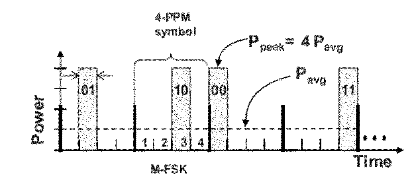
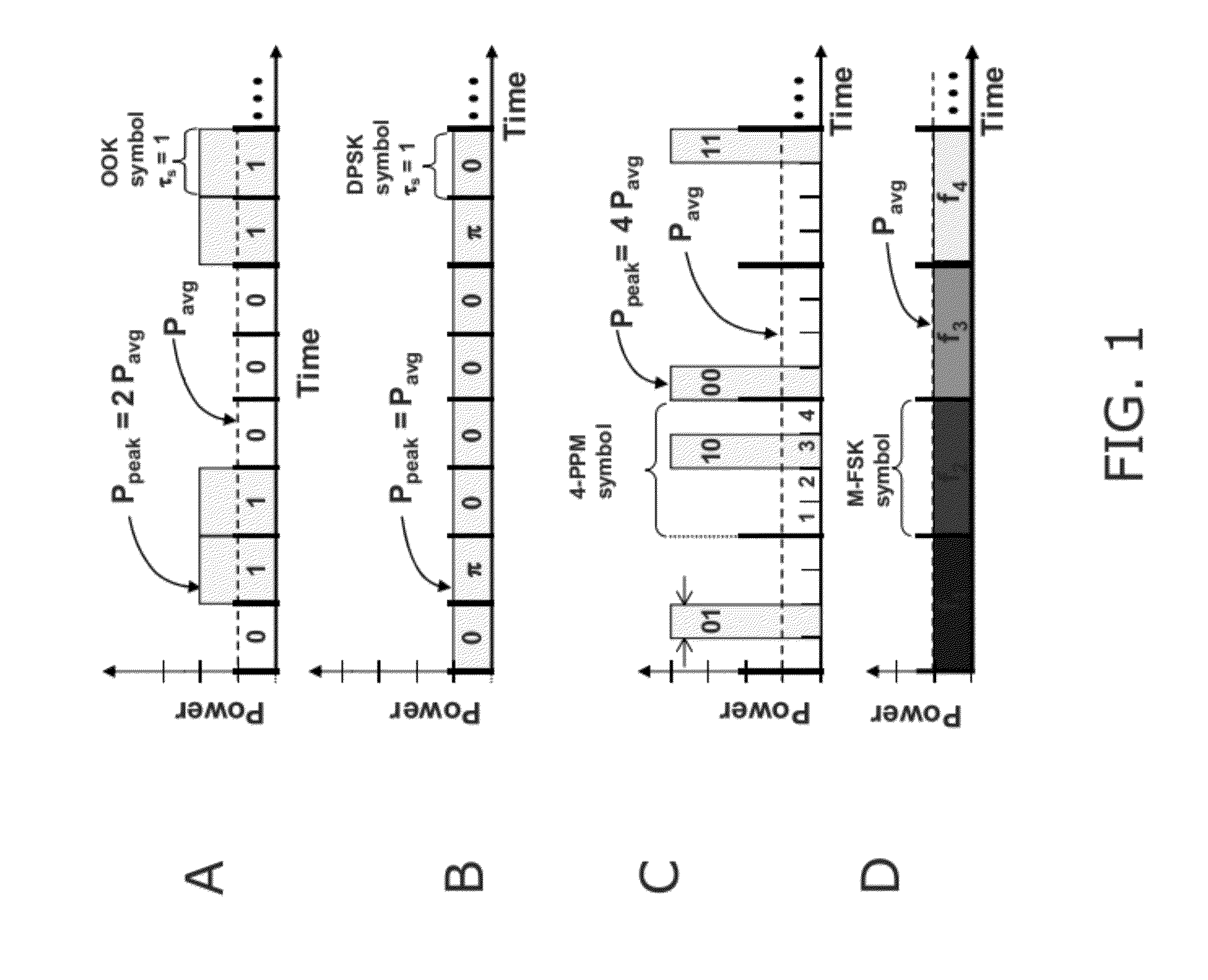
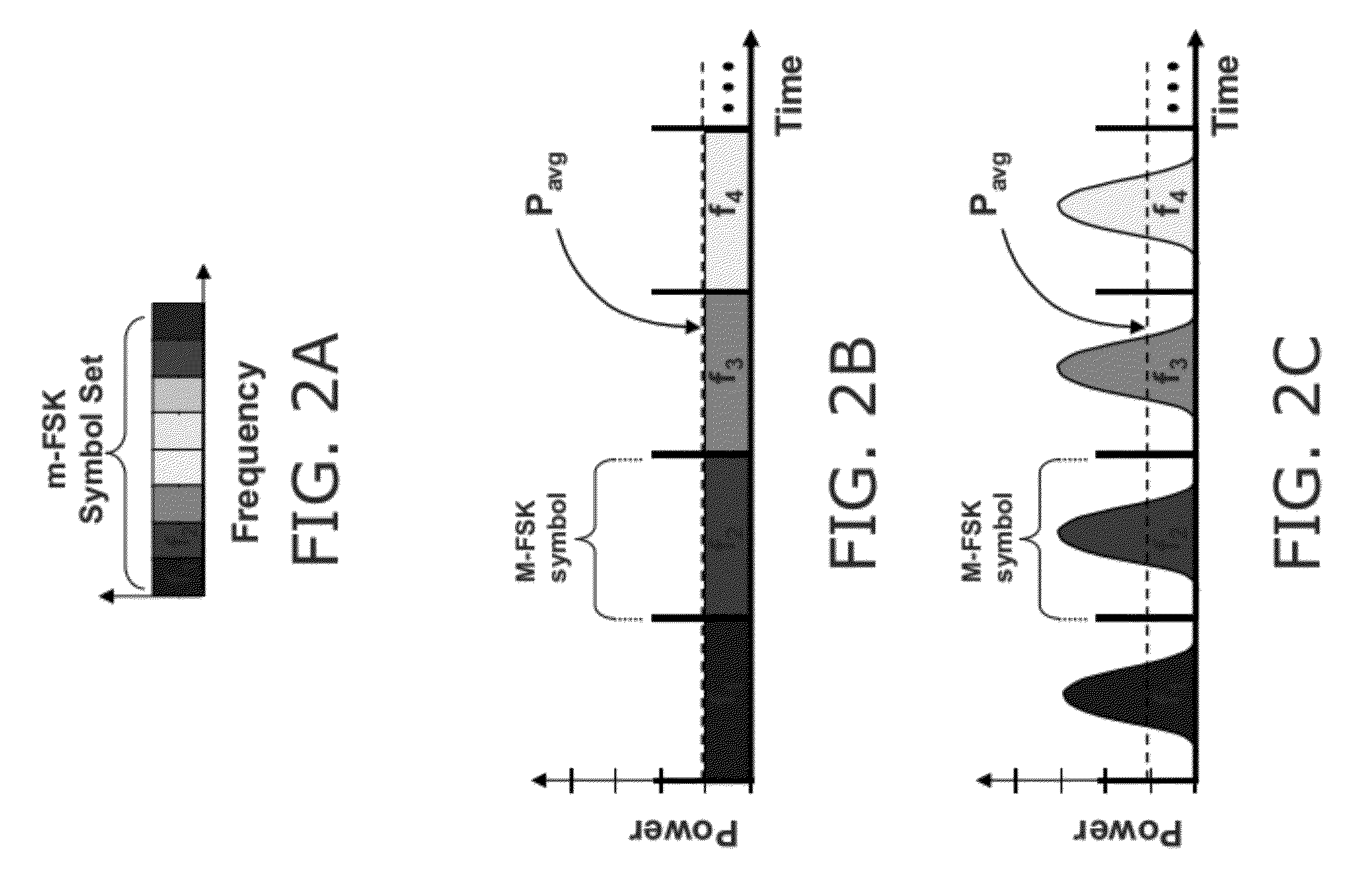
[0035]The orthogonal modulation formats are explained with reference to FIGS. 1A-1D. The term “orthogonal,” as used herein with reference to a modulation format Refers to the property that any two symbols of an orthogonal symbol set, si(t) and sj(t) have the following well known mathematical relationship

∫si(t)sj(t)dt=Esδij

where Es is the energy per symbol and δij is the Kronecher delta function:

δij={0,ifi≠j1,ifi=j.

In other words, different symbols within an orthogonal symbol set have the same energy (Es) but no joint energy, meaning filters may be employed to separate orthogonal symbols without any crosstalk.

[0036]To better understand the benefits afforded by embodiments of this invention, it is instructive to understand the properties of commonly used modulation formats.FIG. 1A is a schematic representation of the On-Off-Keying (OK) modulation format imlementented with NRZ signaling. This is one of the simplest mo...


PUM


Abstract

The present invention provides a simple means of demodulating optical signals, e.g. wideband M-ary orthogonal. The demodulator comprises an optical processor and a comparison module. The optical processor transforms M input optical signals into 2 log2(M) intermediary optical signals and the comparison module determines the logical representation of the input data based on log2(M) binary comparisons of the optical power of the intermediary signals. Example embodiments may be reconfigurable to receive optical signals using M-FSK, M-PPM, M-PolSK, and hybrid M-ary orthogonal modulation formats. Example embodiments also offer small size, weight and power consumption for both free-space and fiber optic environments as well as improved receiver sensitivity and reduced electron bandwidth requirements.

Description

RELATED APPLICATION[0001]This application claims the benefit of U.S. Provisional Application No. 61 / 481,360, filed on May 2, 2011.[0002]The entire teachings of the above application(s) are incorporated herein by reference.GOVERNMENT SUPPORT[0003]This invention was made with government support under FA821-05-C-002 awarded by the United States Air Force. The government has certain rights in the invention.BACKGROUND OF THE INVENTION[0004]The parallelization of optical communications using wavelength division multiplexing (WDM) has led to tremendous increases in fiber-optic channel capacity over the past decade. The use of numerous WDM channels to transmit information leverages the vast available spectrum of the optical channel (such as a guided, e.g., fiber-optic, or unguided, e.g., free space, optical channel) which exceeds many THz, with each channel preferably using a manageable amount of bandwidth (e.g., GHz-class) that may, in practice, be generated with available electronics.[000...

Claims


Application Information

Patent Timeline
Patent Type & Authority Applications(United States)
IPC IPC(8): H04B10/06
CPCH04B10/67
Inventor CAPLAN, DAVID O.
Owner MASSACHUSETTS INST OF TECH
Why Eureka
Try Eureka