
Ball and socket joint for a vehicle

a technology for vehicles and sockets, applied in the direction of shafts, pivots, couplings, etc., can solve the problems of undesired plastic deformation of the first ball socket part, and achieve the effects of low contact pressure, high frictional torque, and special shap

Active Publication Date: 2012-11-08
ZF FRIEDRICHSHAFEN AG
View PDF11 Cites 13 Cited by
  • Summary
  • Abstract
  • Description
  • Claims
  • Application Information

AI Technical Summary

Benefits of technology

[0013]According to one embodiment of the invention, the second ball socket part comprises a main body and at least one bearing section, which is elastically connected to the main body and by means of which the second ball socket part rests against the joint ball. In this embodiment, a gap formation can be avoided under load even for the second ball socket part.
[0018]The joint ball lies against the ball socket preferably with a lubricant disposed therebetween. The lubricant is advantageously introduced into the ball socket. The lubricant is a traction oil, for example, and in particular increases the friction coefficient under load.
[0021]The adjusting device can be a hydraulic or electric adjusting device. For example, the adjusting device can comprise piezoelectric elements, by means of which the first ball socket part can be moved relative to the second ball socket part. According to a development of the invention, the adjusting device has a drive and one or at least one transmission, which comprises a first transmission part having ball tracks, which rise in the axial direction and extend curved, in particular in a spiral shape, around a rotational axis oriented in the axial direction and in each of which at least one ball is guided, and a second transmission part, which is in contact with the balls, which are disposed between the transmission parts in the axial direction, wherein the balls and the first transmission part can be rotated about the rotational axis relative to each other by means of the drive. If the balls and the first transmission part are rotated about the rotational axis relative to each other, the balls are moved along the ball tracks, so that the axial distance between the transmission parts changes as a result of the axial rise of the ball tracks. The adjusting device thus forms an axial stroke device, which can be driven by the drive and by means of which in particular the first ball socket part can be moved relative to the second ball socket part in the axial direction. This embodiment of the adjusting device can be designed very compact and avoids the leakage problems associated with a hydraulic system. The drive is preferably a motor, in particular an electric motor.
[0024]According to one embodiment of the invention, the first transmission part can be driven by the drive, in particular can be rotated by the drive about the rotational axis relative to the balls. The drive is preferably connected to the first transmission part, an additional transmission, which is designed for example as a planetary transmission, being disposed therebetween. A higher transmission ratio can be achieved by means of the additional transmission. If the additional transmission is designed as a planetary transmission, a relatively flat and compact construction can also be achieved. This enables the use of a relatively small drive, so that the adjusting device can be integrated into the ball and socket joint. While the first transmission part is rotated, the balls run along the ball tracks, wherein the axial distance between the transmission parts is changed as a result of the ball tracks of the first transmission part rising in the axial direction. Because the ball tracks of the first transmission part are curved around the rotational axis, in particular the distance of the balls from the rotational axis also changes.
[0029]The invention preferably creates a ball and socket joint for high frictional torques that is characterized by a special shape, material selection, and surface quality. The friction of the joint ball in the ball socket preferably can be self-reinforced by the wedge effect. In particular, the ball and socket joint according to the invention has the following advantages:
[0032]Positive driving dynamics effects can be achieved, in particular during stable straight driving. Furthermore, steering vibrations can be damped and the pitch behavior of the vehicle can be improved.

Problems solved by technology

However, because it should be permissible to also reduce this pressure again, plastic deformation of the first ball socket part is undesired, so according to the invention the connection of the bearing section to the main body is elastic.

Method used


Image

  • Ball and socket joint for a vehicle
  • Ball and socket joint for a vehicle
  • Ball and socket joint for a vehicle

Examples


Embodiment Construction

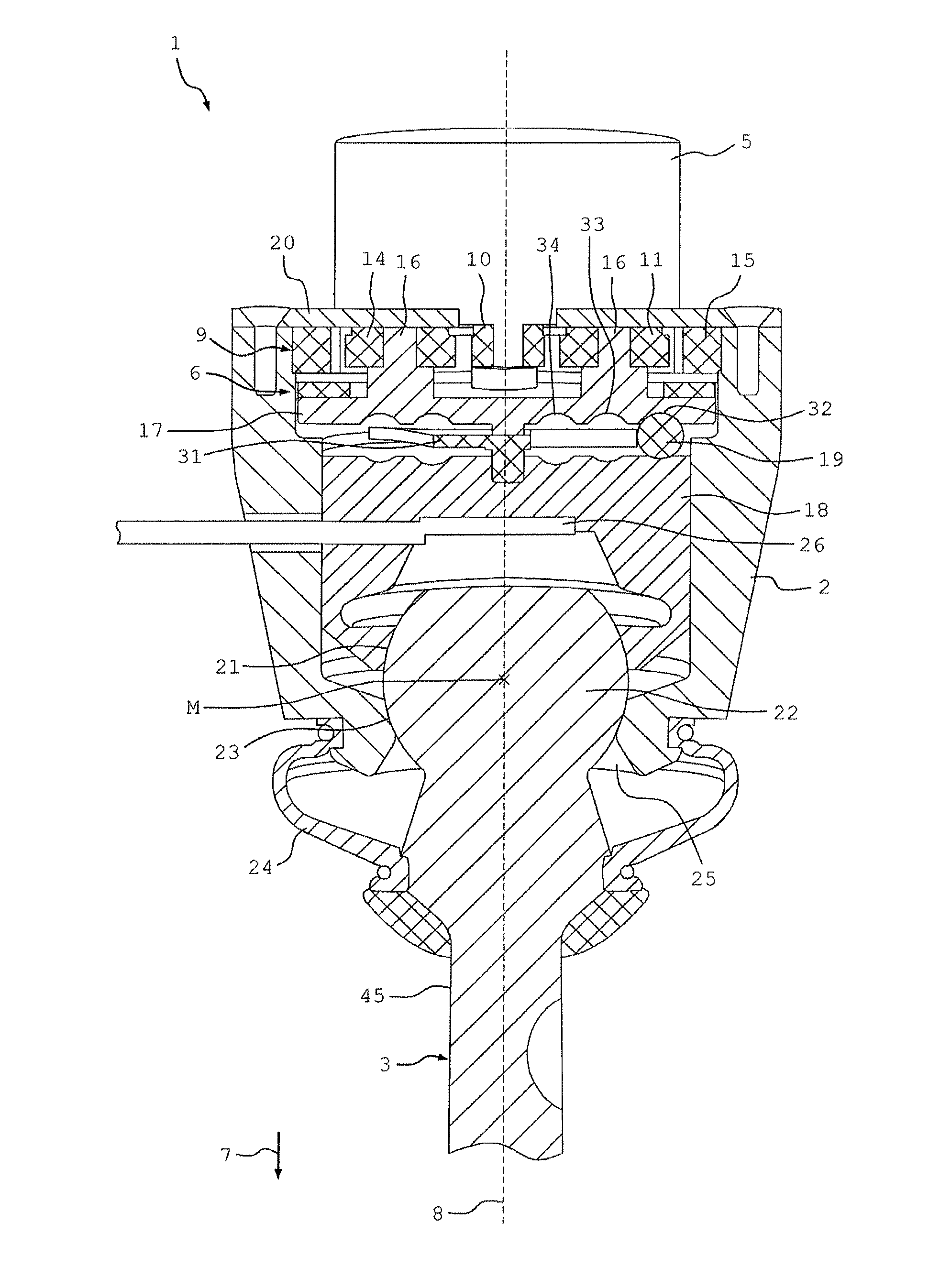
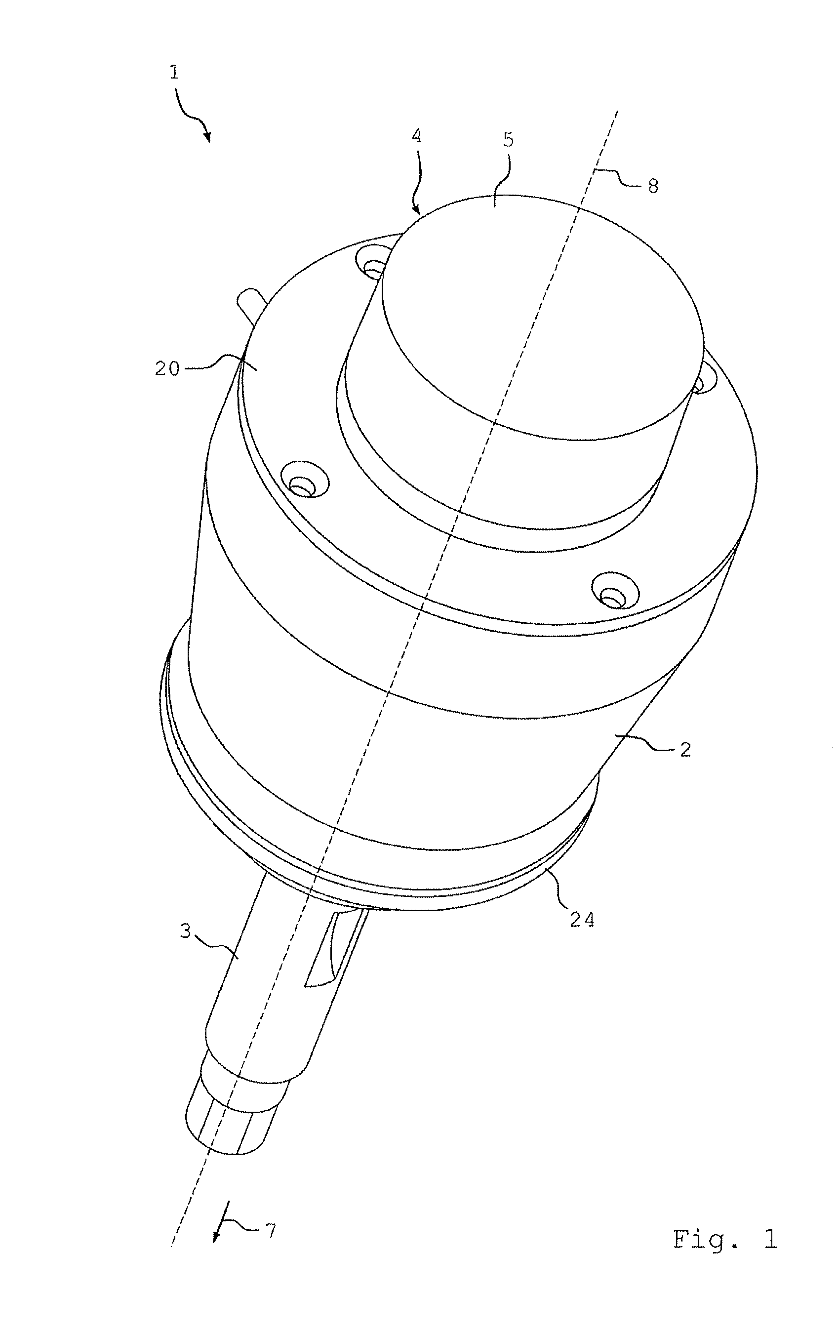
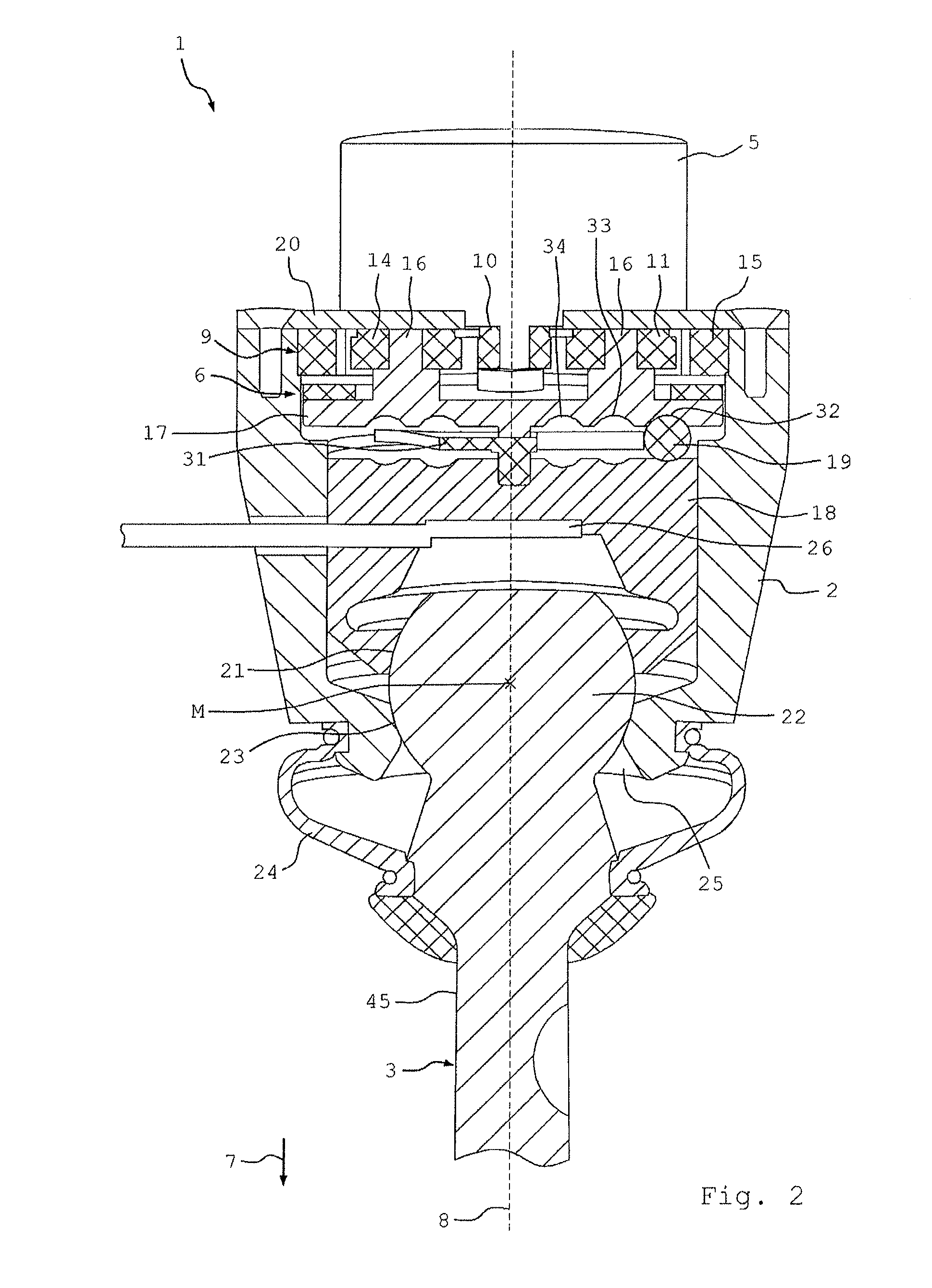
[0040]Different depictions and partial depictions of a ball and socket joint 1 according to an embodiment of the invention can be seen in FIGS. 1 to 6, the ball and socket joint having a housing 2, in which a ball pin 3 is supported in a rotatable and pivotable manner. The friction of the ball pin 3 during motion relative to the housing 2 can be varied by means of an adjusting device 4, which is rigidly connected to the housing 2 and has an electric motor 5 and a transmission arrangement 6 (see FIG. 2). The central longitudinal axis of the ball and socket joint 1 extending in an axial direction 7 is marked with the reference symbol 8.

[0041]A section of the ball and socket joint 1 along the longitudinal axis 8 can be seen in FIG. 2, wherein the motor 5 is depicted uncut. The transmission arrangement 6 has a planetary transmission 9, which can be seen in a perspective depiction in FIG. 3. The planetary transmission 9 comprises a sun gear 10, which can be rotated about the longitudinal...


PUM


Abstract

A ball and socket joint comprises a joint ball which is enclosed and rotationally supported by a ball socket. The ball socket has two ball socket parts that move relative to one another in an axial direction. The ball socket parts acts on different sides of the joint ball that are opposite one another in the axial direction. A controllable adjusting device bias the two ball socket parts, relative to one another in the axial direction, so that pressure exerted on the joint ball by the twp ball socket parts can be varied. At least a first of the ball socket parts comprises a main body and at least one bearing section, which is elastically connected to the main body and by which the first ball socket part rests against the joint ball.

Description

[0001]This application claims priority from German patent application serial no. 10 2011 075 324.9 filed May 5, 2011.FIELD OF THE INVENTION[0002]The invention relates to a ball and socket joint for a vehicle, comprising a ball pin, which has a joint ball, a ball socket, which encloses the joint ball and is provided with a pin opening and in which the joint ball of the ball pin is rotatably supported, the ball pin extending through the pin opening, wherein the ball socket has two ball socket parts that can be moved relative to each other in an axial direction, the ball socket parts acting on different sides of the joint ball that are opposite each other in the axial direction, and a controllable adjusting device, by means of which the ball socket parts can be moved relative to each other in the axial direction so that a pressure exerted on the joint ball by the ball socket parts can be varied.BACKGROUND OF THE INVENTION[0003]From DE 102 45 983 A1, a ball and socket joint is known, co...

Claims


Application Information

Patent Timeline
IPC IPC(8): F16C11/06
CPCF16C11/0647Y10T403/32721F16C11/0652
Inventor ERSOY, METINVORTMEYER, JENS
Owner ZF FRIEDRICHSHAFEN AG
Learn More