Actuator available in controlled environment

a technology of actuators and controlled environments, applied in the field of actuators, can solve the problems of difficult to keep the high cleanliness class, and achieve the effects of less weight and height, high mechanical strength, and highly accurate position control

Active Publication Date: 2012-11-15
NIPPON THOMPSON
View PDF13 Cites 27 Cited by
  • Summary
  • Abstract
  • Description
  • Claims
  • Application Information

AI Technical Summary

Benefits of technology

[0015]With an actuator befitted to work in a clean environment constructed as stated earlier, the fundamental construction constituted with the elongated bed of U-shape in a transverse section and the slider moveable lengthwise in the bed through rolling elements, as being high in mechanical strength, is favorable for highly accurate position control and conformable to high speed operation and high acceleration/deceleration. Further, the fundamental construction as stated just above helps make the actuator less in weight and height and further compact in construction. In the actuator of the present invention, the enclosure to enclose the bed therein is constructed to get its airtightness more ensured. Especially, the packings are installed in the conventionally existing T-slots in the side walls of the bed to securely seal up the clearances between the bed and the side coverings. In addition, the sensors are placed outside the enclosure to make it possible to enclose both the bed and the slider with the housing simple in construction. As a result, the volume inside the enclosure in which the slider moves in the bed as a whole may be less so that the purification of the air with airborne contaminant to accomplish a high cleanliness class requires less amount of sucked air. With the actuator in which the side plate is depressed inwards than an outward surface of the side plate at a location above the side wall of the bed to form a groo

Problems solved by technology

Further, the prior actuator described in the patent literature 2 was hard to keep the high cleanliness class in various modern machines in which the slider operated with high

Method used


Image

  • Actuator available in controlled environment
  • Actuator available in controlled environment
  • Actuator available in controlled environment

Examples


Embodiment Construction

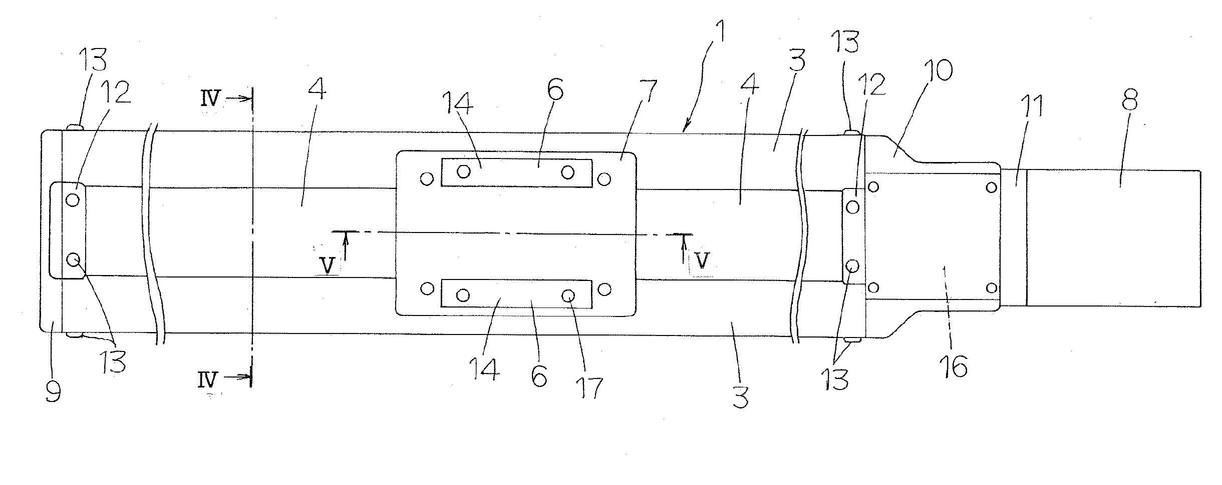
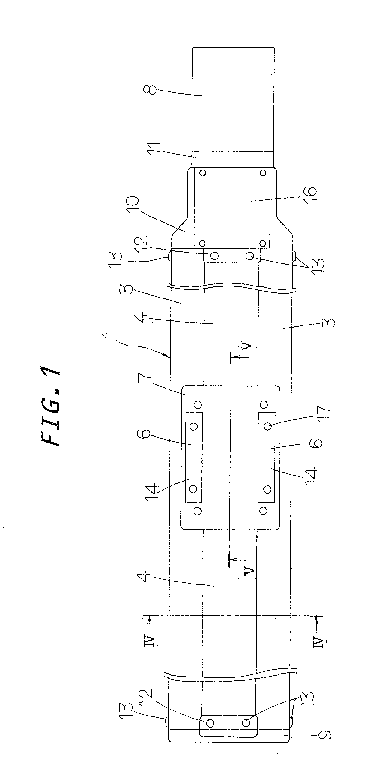
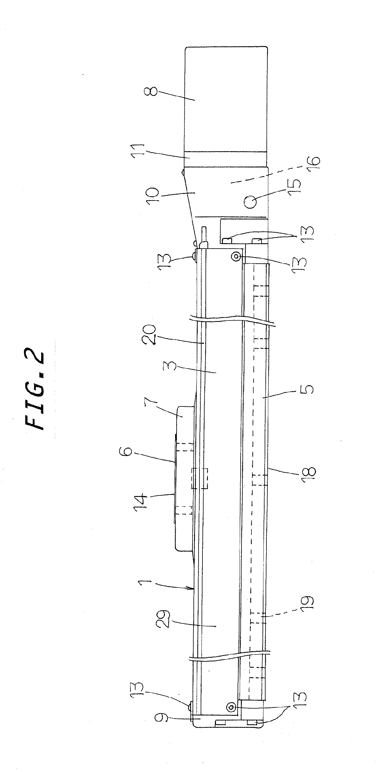
[0027]The actuator befitted to work in clean environment of the present invention is intended to be used as position controls in a diversity of machinery such as semiconductor manufacturing equipment, LCD panel manufacturing equipment and so on, which are needed to work in any controlled atmosphere including clean rooms, laboratories and the like.

[0028]Referring now in detail to the accompanying drawings, an actuator designed to work in a clean environment according to the present invention will be explained below. While based on the actuator serving as the accurate position-control table disclosed in the patent literature 1 as stated earlier, an actuator befitted to work under clean environment or atmosphere of the present invention, called clean environmental actuator hereinafter, has been developed in which the actuator is encased or enclosed with a housing or enclosure constituted with sealing members including a variety of coverings and so on to endure working in clean environm...


PUM


Abstract

A clean environmental actuator is less in weight, height in transverse section and compact in construction, even with ensuring accurate position control and conformable to high speed operation and high acceleration/deceleration. Both a bed and a slider are stowed in an enclosure and packings are in T-slots in side walls of the bed to seal clearances between the bed and the enclosure. The enclosure is composed of an end bracket to cover one end of the bed, a motor bracket to cover another end of the bed, a pair of side coverings to enclose the side surfaces and tops of the side walls of the bed, a sealing panel to cover an upward opening between the side coverings, and a table covering to overlay an area of the sealing panel lying on the slider and side areas of the table bulging out from side edges of the sealing panel.

Description

FIELD OF THE INVENTION[0001]The present invention relates generally to an actuator intended to operate in controlled or contamination-free environment. More particularly, it relates to an actuator available in controlled environment in which an elongated bed is enclosed hermetically inside an airtight enclosure and a table system composed of a slider and a drive unit to move a table built integral with the slider in lengthwise direction of the bed towards a desired position to provide accurate position control.BACKGROUND OF THE INVENTION[0002]Most actuators have conventionally found a diversity of applications including assembling apparatus, measurement instruments, various machines, industrial robots, semiconductor manufacturing equipments and so on to drive and guide a workpiece for linear back-and forth movement. The actuators used of late years in machinery as recited earlier have need of a high cleanliness class because of desired to work in a controlled environment as in a cle...

Claims


Application Information

Patent Timeline
IPC IPC(8): F16H19/02
CPCF16H25/2204F16H2025/2034F16H2025/2075H02K7/06Y10T74/18712F16C29/088Y10T74/18568Y10T74/18656F16C29/02
Inventor SAKAI, TETSUYA
Owner NIPPON THOMPSON
Why Eureka
Try Eureka