Variable valve timing control apparatus of internal combustion engine

a technology of timing control apparatus and internal combustion engine, which is applied in mechanical equipment, valve arrangements, machines/engines, etc., can solve the problems of increasing the thickness of the shoe, increasing the relative rotational angle between the housing and the vane, and reducing the strength of the shoe, so as to reduce the hydraulic pressure and increase the number of vanes

Inactive Publication Date: 2012-11-15
HITACHI AUTOMOTIVE SYST LTD
View PDF4 Cites 20 Cited by
  • Summary
  • Abstract
  • Description
  • Claims
  • Application Information

AI Technical Summary

Benefits of technology

[0005]In recent years, it has been required that a thickness in the circumferential direction of each shoe be as thin as possible, in order to increase the number of the vanes by a request to reduce the hydraulic pressure that is supplied to each chamber and in order to obtain a large relative rotational angle of the vane member with respect to the housing.
[0008]It is therefore an object of the present invention to provide a variable valve timing control apparatus of the internal combustion engine, which is capable of ensuring the strength of the shoe while sufficiently securing the relative rotational angle between the housing and the vane member.

Problems solved by technology

However, if the thickness of each shoe is formed thin, its strength decreases.
Because of this, the shoe might be bent and deformed when the vane is pressed against the shoe from the circumferential direction, and there is a possibility that a desired relative rotational angle will not be obtained.
However, there is a trade-off between an increase in the thickness of the shoe and an increase in the relative rotational angle between the housing and the vane.
Thus, if the thickness of the shoe is thicken, it is difficult to obtain the large relative rotational angle between the housing and the vane.

Method used


Image

  • Variable valve timing control apparatus of internal combustion engine
  • Variable valve timing control apparatus of internal combustion engine
  • Variable valve timing control apparatus of internal combustion engine

Examples


first embodiment

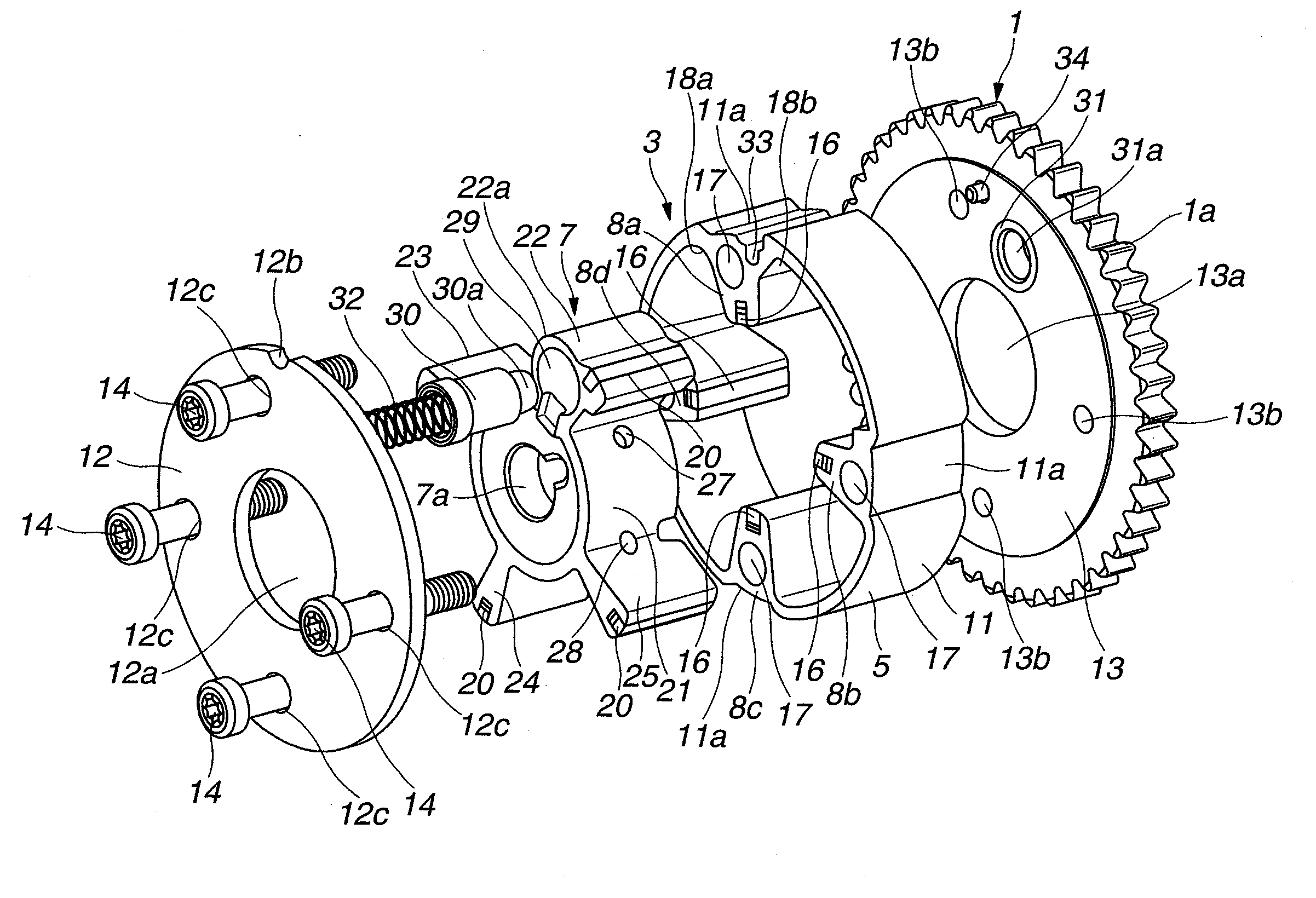
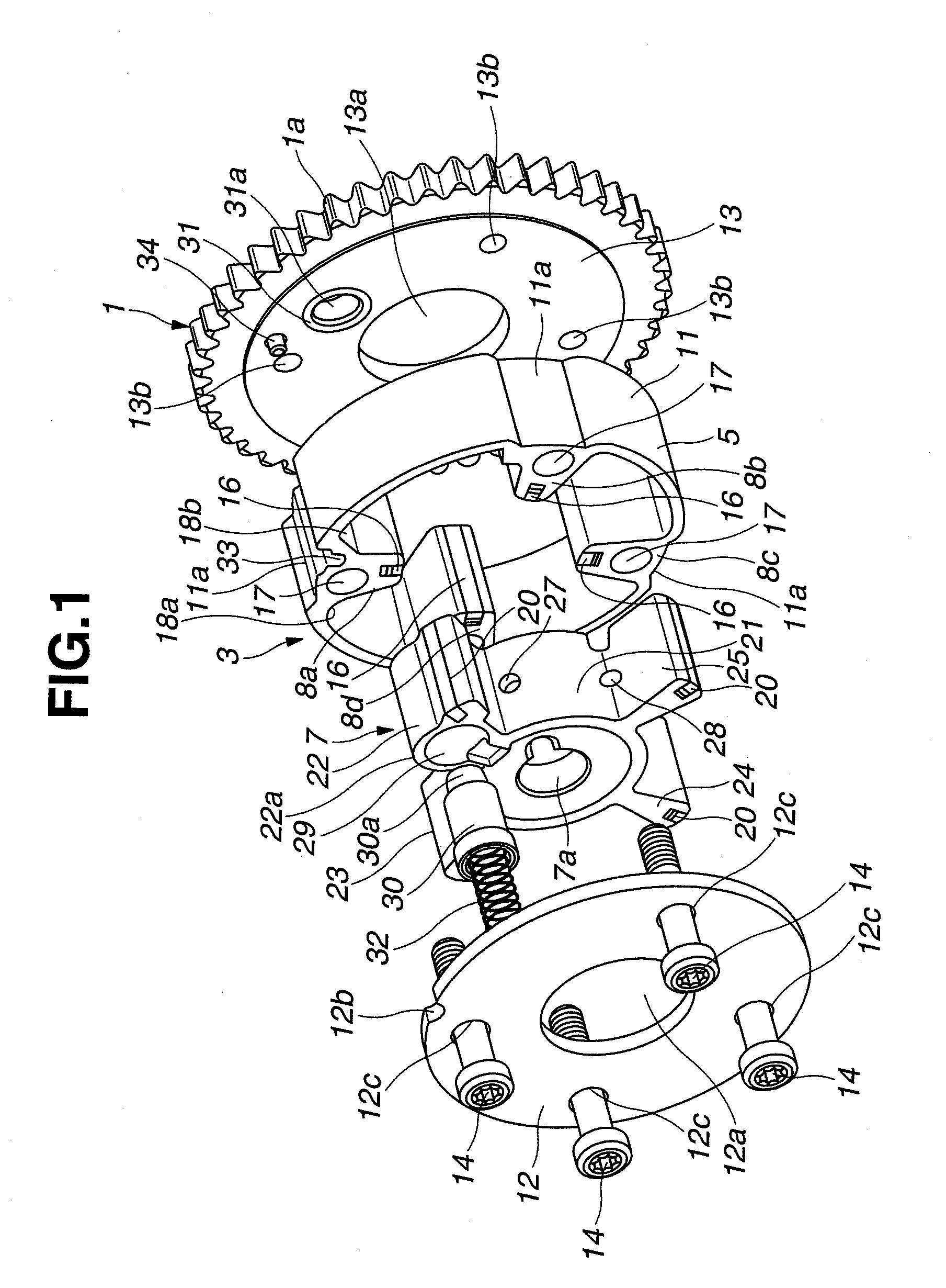
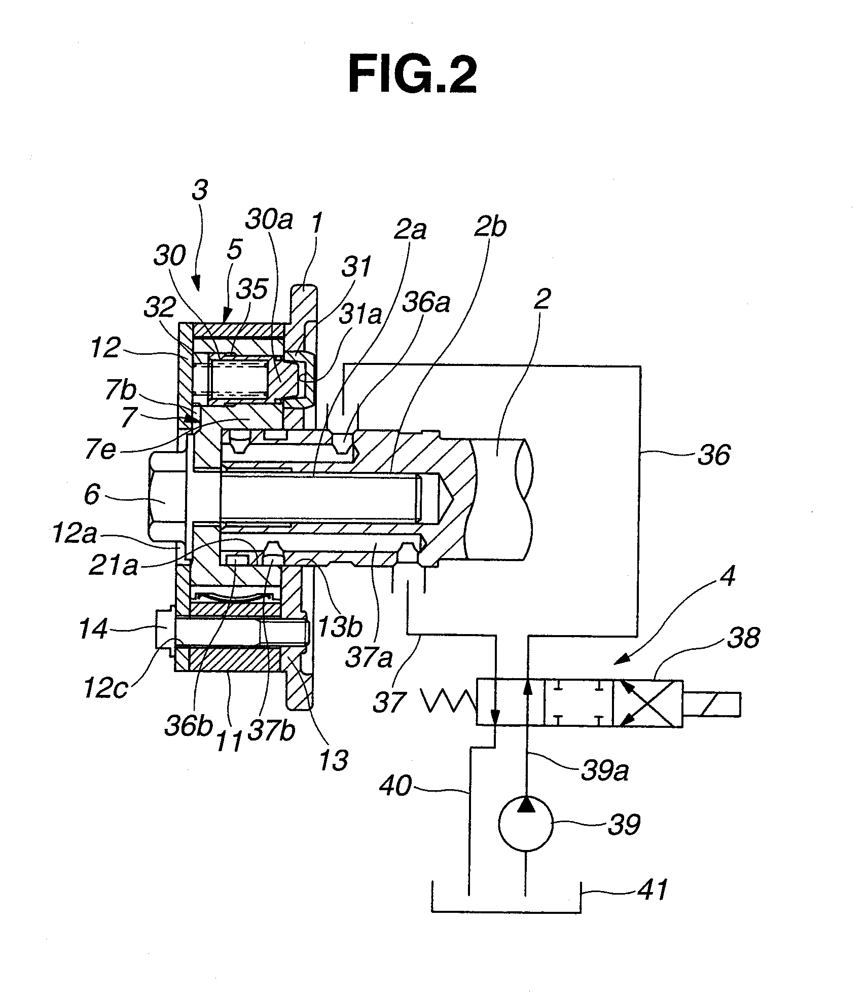
[0022]FIGS. 1 to 5 show a first embodiment of the variable valve timing control apparatus. The variable valve timing control apparatus has a sprocket 1 that is driven and rotates by an engine crankshaft (not shown) through a timing chain, a camshaft 2 that is capable of rotating relative to the sprocket 1, a relative angular phase control mechanism (simply, a phase converter or a phase-change mechanism) 3 disposed between the sprocket 1 and the camshaft 2 and changing or controlling a relative rotational position between the sprocket 1 and the camshaft 2, and a hydraulic circuit 4 that actuates the phase-change mechanism 3.

[0023]The camshaft 2 is rotatably supported by a cylinder head (not shown) through a camshaft bearing. The camshaft 2 has a plurality of driving cams, each of which actuates an intake valve through a valve lifter. Each driving cam is formed integrally with the camshaft 2 at a certain position on an outer peripheral surface of the camshaft 2. Further, the camshaft ...

second embodiment

[0082]FIGS. 6 and 7 show a second embodiment of the variable valve timing control apparatus. A basic structure is the same as that of the first embodiment. However, in the second embodiment, the relative rotational position of the most-advanced angle side of the vane member 7 is limited by the fact that, as shown in FIG. 7, the narrow second vane 23, which is adjacent to the first vane 22 in the counterclockwise direction, touches a side surface at the thick portion 18a side of the first shoe 8a when the vane member 7 rotates to the maximum to the most-advanced angle side (i.e. in the clockwise direction) with respect to the housing 5.

[0083]That is, as same as the first embodiment, the first shoe 8a is provided with the first thick portion 18a and the thick part 18b at the both corners of the first shoe 8a.

[0084]On the other hand, as for the second vane 23, a protruding portion 62 is formed integrally with a base portion side surface, at the first shoe 8a side, of the second vane 2...


PUM


Abstract

A variable valve timing control apparatus of an internal combustion engine, has a housing having a plurality of shoes and a vane member having a plurality of vanes dividing each working fluid chamber formed between adjacent two shoes into advance and retard oil chambers. The vane member rotates to an advanced angle side and to a retarded angle side relative to the housing by selectively supplying or exhausting hydraulic pressure in or from the advance oil chamber and the retard oil chamber. A most-advanced angle position and a most-retarded angle position are limited by the fact that one vane touches one shoe from a circumferential direction. Radius of curvature of one of both corners of a base part of the one shoe, which is a corner located at a side where the one vane does not touch, is set to be greater than those of corners of the other shoes.

Description

BACKGROUND OF THE INVENTION[0001]The present invention relates to a variable valve timing control apparatus of an internal combustion engine, which variably controls open and closing timing of an intake valve and / or an exhaust valve of the engine in accordance with an engine operating condition.[0002]As one of generally used variable valve timing control apparatuses, a vane type variable valve timing control apparatus disclosed in Japanese Patent Provisional Publication No. 2002-295212 (hereinafter is referred to as “JP2002-295212”) is known.[0003]This vane type variable valve timing control apparatus has a housing to which a turning force is transmitted from an engine crankshaft and a vane member which is rotatably housed in the housing and is secured to an end portion of a camshaft. Further, a plurality of shoes are formed on an inner peripheral surface of the housing so as to protrude in a radially inward direction. Advance oil chambers and retard oil chambers are defined between...

Claims


Application Information

Patent Timeline
Patent Type & Authority Applications(United States)
IPC IPC(8): F01L1/34
CPCF01L1/3442F01L2001/34469F01L2001/34456
Inventor WATANABE, ATSUSHI
Owner HITACHI AUTOMOTIVE SYST LTD
Why Eureka
Try Eureka