Image processing apparatus and image registration method

a technology of image processing and image registration, applied in the field of image processing apparatus, can solve the problems of insufficient reflection of histological changes in soft tissue images, inability of the apparatus to clearly render the morphology of the organ, and limited image pickup area of the apparatus, so as to achieve a high degree of precision and registration. the effect of high degr

Inactive Publication Date: 2012-11-15
HITACHI LTD
View PDF6 Cites 12 Cited by
  • Summary
  • Abstract
  • Description
  • Claims
  • Application Information

AI Technical Summary

Benefits of technology

[0022]According to the present invention, in registration between the first and second images captured by different apparatuses, from one image, an image similar to the other image is generated at high speed. Thus, the pixel values, shapes, and field of views of the same site of the subject, which is an imaging target, can be easily compared. As a result, automatic, high-speed, and high degree of precision registration can be performed between the images.
[0023]Further, in the process of generating a similar image, an area to be positioned is specified in the original image and added thereto. Thus, registration with higher degree of precision can be performed between the images.

Problems solved by technology

However, the images obtained do not sufficiently reflect histological changes in soft tissue.
However, these apparatuses cannot clearly render the morphology of an organ compared to x-ray CT apparatuses, MRI apparatuses, and the like.
However, the image pickup area thereof is limited depending on the shape of the probe.
Further, a US image includes much noise and thus does not clearly show the morphology of soft tissue compared to images clearly showing the morphology, such as a CT image and MRI image.
However, when images of the same subject are captured by multiple apparatuses, the images obtained do not have the same pixel value or the same distribution even at the same site.
This makes registration difficult.

Method used


Image

  • Image processing apparatus and image registration method
  • Image processing apparatus and image registration method
  • Image processing apparatus and image registration method

Examples


first embodiment

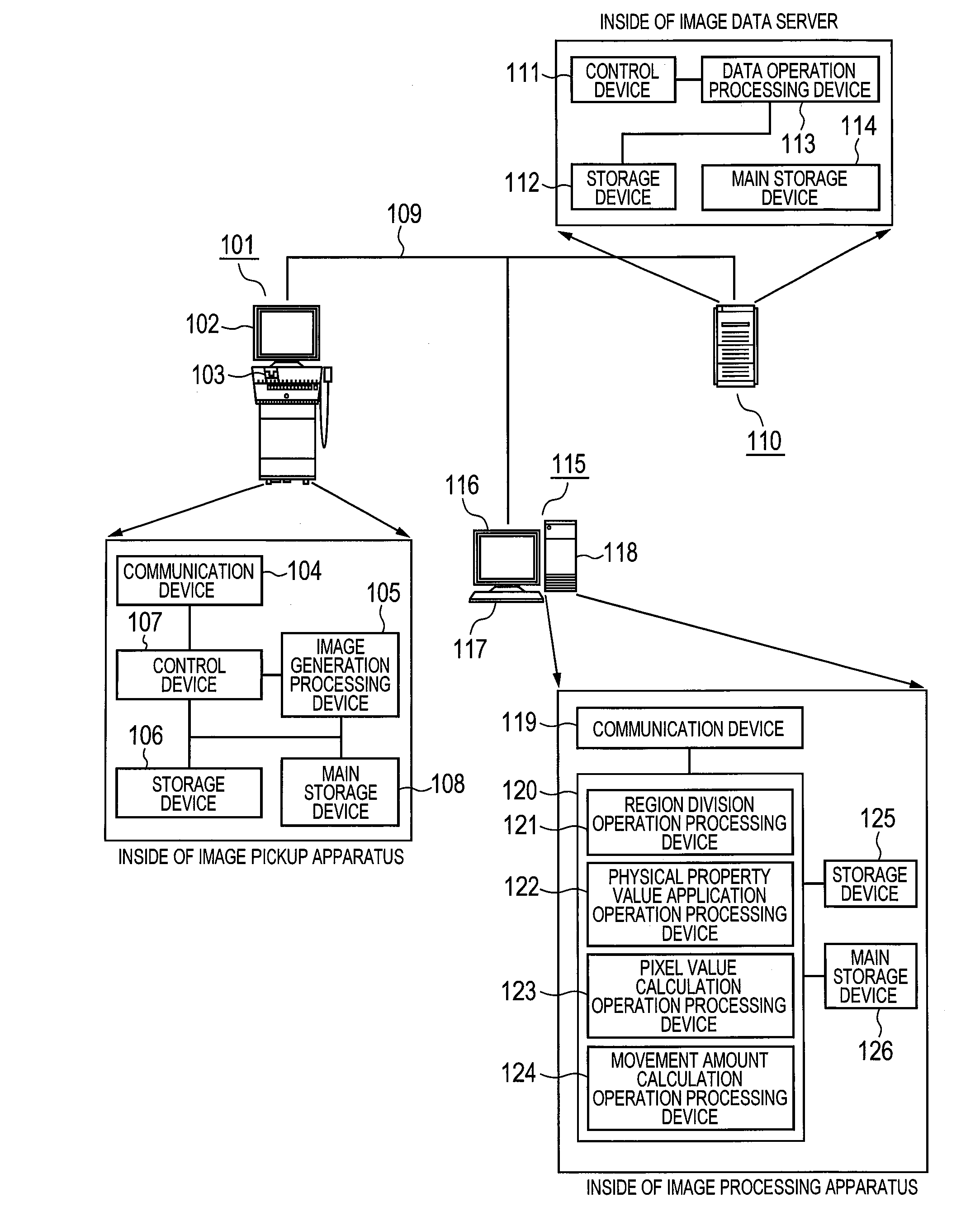
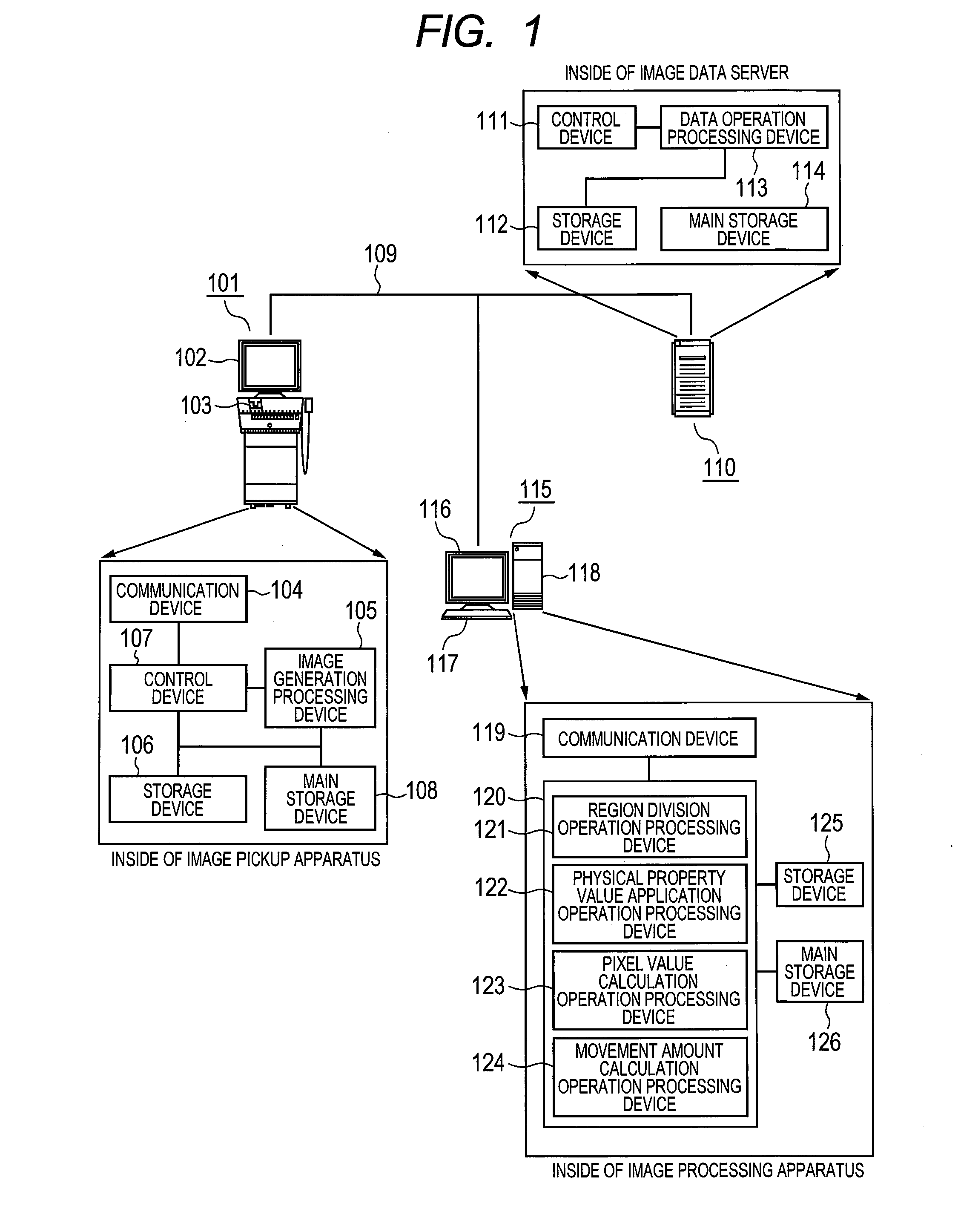
[0037]The overall configuration of an image registration system according to a first embodiment is shown in FIG. 1. First, devices included in the system will be described. An image pickup apparatus 101 serving as an image diagnosis apparatus includes a main body thereof, a monitor 102 serving as a display for displaying a captured image or parameters required for image capture, and input means 103 for giving an instruction to the image pickup apparatus 101 through a user interface displayed on the monitor 102. The input means 103 is typically a keyboard, mouse, or the like. A user interface which is typically used on the monitor 102 is a graphical user interface (GUI).

[0038]As shown, the main body of the image pickup apparatus 101 further includes a communication device 104 for communicating with the inside of the main body, an image generation processing device 105 for generating an image from image capture data, a storage device 106 for storing data such as a processing result or...

second embodiment

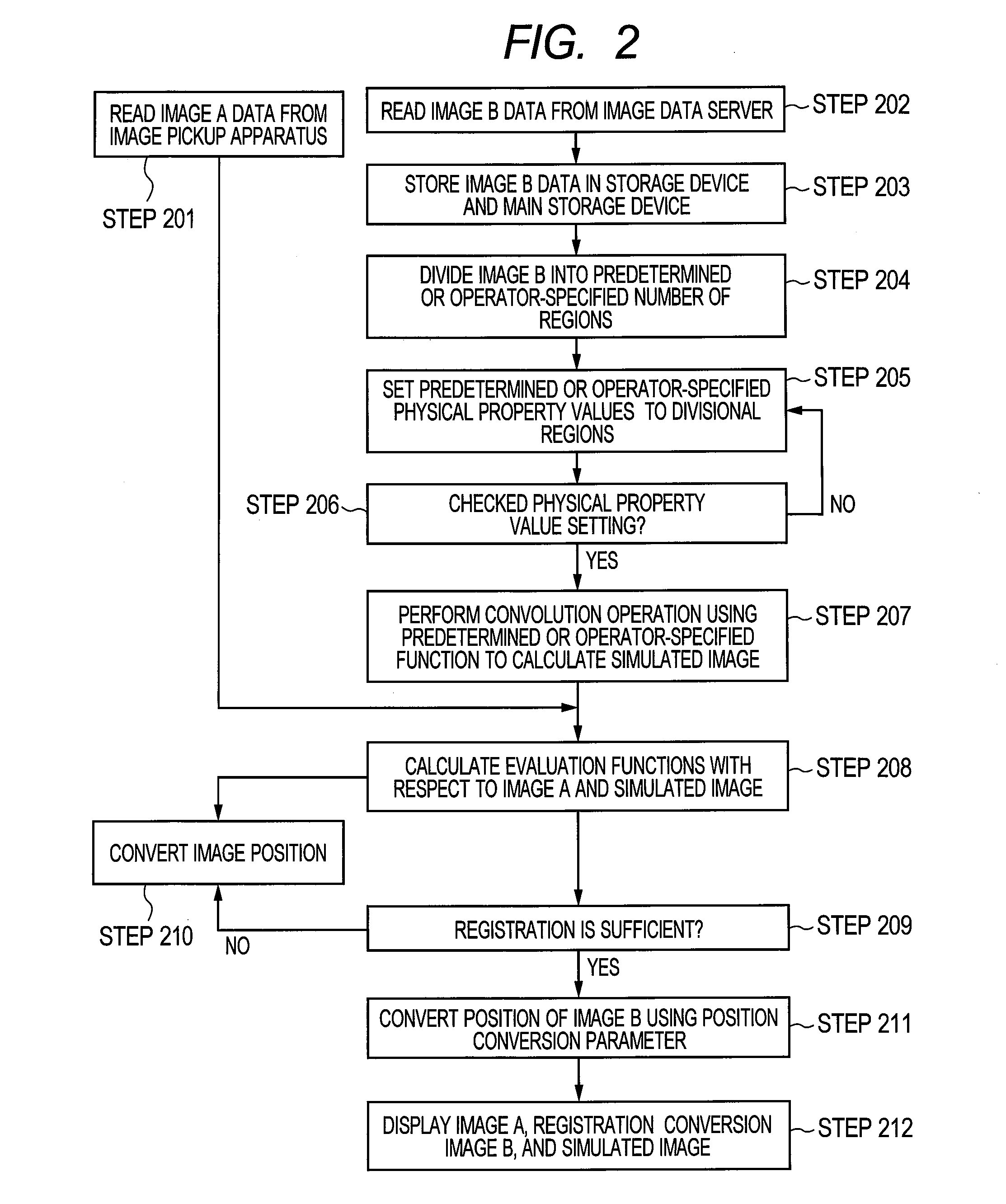
[0068]Next, a method where, in step 205 of FIG. 2, the operator newly specifies an area which is not rendered in the image and sets a physical property value to the area will be described as a second embodiment using FIGS. 8A and 8B. The operator additionally specifies an area (additional area 5) in an image 802 which is obtained by dividing image data B801 into regions, using the input means 117 via a user interface displayed on the monitor 116 by the operator. Thus, an image 803 can obtained. A physical property value (values) is set to the specified area. Thus, even when the site of interest rendered in the image data A, such as an organ or disease site, is not rendered in the image data B, the site of interest can be rendered in the pseudo image generated in step 206 by adding the shape and physical property thereof to the image B using the above-mentioned method. Since the site of interest is rendered on the pseudo image, registration precision can be improved by performing reg...


PUM


Abstract

In the process of a registration between first and second images captured by different image pickup apparatuses, even if corresponding parts have different pixel values, different shapes and different field of view, the registration can be carried out with high speed and high degree of precision. In order to perform the registration between the first and second images, either of the first and second images is divided into segmented regions, and given physical property values are set to the segmented regions. Further, an image (pseudo image) having similar pixel values, shapes and field of view to the other image is created, and the pseudo image and the second image that have the same features are positioned, thereby performing the registration between the first and second images.

Description

TECHNICAL FIELD [0001]The present invention relates to an image processing apparatus and in particular to an image registration technology for performing registration between images obtained by multiple image diagnosis apparatuses.BACKGROUND ART [0002]Medical image diagnosis allows body information to be obtained noninvasively and thus has been widely performed in recent years. Three-dimensional images obtained by various types of image diagnosis apparatuses such as x-ray computer tomography (CT) apparatuses, magnetic resonance imaging (MRI) apparatuses, positron emission tomography (PET) apparatuses, and single photon emission computed tomography (SPECT) apparatuses have been used in diagnosis or follow-up. X-ray CT apparatuses generally can obtain images having less distortion and high spatial resolution. However, the images obtained do not sufficiently reflect histological changes in soft tissue. On the other hand, MRI apparatuses can render soft tissue with high contrast. PET ap...

Claims


Application Information

Patent Timeline
Patent Type & Authority Applications(United States)
IPC IPC(8): G06K9/32G09G5/377G06T15/06
CPCA61B6/025A61B6/463A61B6/5241A61B8/5238G06T2207/10072G06T2207/10136G06T2207/30004A61B6/5247G06T7/0024G06T3/0068G06T7/30
Inventor MATSUZAKI, KAZUKISETO, KUMIKONAGAMINE, YOSHIHIKOSASAKI, HAJIME
Owner HITACHI LTD
Why Eureka
Try Eureka