Portable fundus camera

a fundus camera and camera body technology, applied in the field of imaging, can solve the problems of visual loss, many factors, and often feared untoward health event of vision loss, and achieve the effects of less data loss, convenient use, and improved patient car

Active Publication Date: 2012-11-15
LUMETRICS
View PDF0 Cites 82 Cited by
  • Summary
  • Abstract
  • Description
  • Claims
  • Application Information

AI Technical Summary

Benefits of technology

[0019]The present invention meets this need by providing a compact portable fundus camera device. The camera can be used by individuals of varying backgrounds. For example, a retina specialist might utilize one such device in each exam lane to speed patient flow; optometrists or general ophthalmologists might find the device economically most favorable as the only mode of photographic documentation of the fundus in their practices; and a primary care provider might use it to document and follow childhood diabetics and patients with other conditions that affect the eyes. The camera enables a user to obtain one or more digital images of the fundus of a patient, deliver such images electronically to an expert reader of such images, and consult with the expert for advice as needed. Health aides, technicians, or nurses may be trained to use the camera to obtain retinal photographs of underserved populations.
[0020]In these settings, the images may be stored and digitally transmitted to qualified image readers to determine the need for further patient observation and / or referral to other medical specialists. The camera is compatible with hand held computing and image viewing platforms such as an iPhone®, or Android™ phone, and can be easily integrated into the growing and dynamic field of remote health monitoring. In so doing, the Applicants' camera can play an important role in helping improve the quality of medical outreach programs as well as reduce rates of blindness and visual disability worldwide.
[0021]Additionally, the Applicants' camera particularly benefits a growing segment of our populace, the aging population. The instant camera device has utility for population based screening for potentially blinding retinal and optic nerve diseases, with the potential for significant health and direct and indirect medical cost savings in the geriatric population.
[0029]Furthermore, in accordance with this invention, other ophthalmic and medical imaging systems such as corneal topography, tomography, keratometry, pupillometry, aberrometry, pachymetry, and autorefraction can be miniaturized to a hand held device that interfaces with a hand held portable computing platform, such as an iPhone® or Android. The integration of these technologies with hand held computing systems will allow for safer patient care (e.g., direct integration with electronic digital files), less loss of data, and ease of use for technicians, physicians and other examiners. In all cases, the direct diagnostic modality is converted to a portable and hand held system compatible with iPhone®, Android™, and similar platforms. Software applications can be downloaded into the device to manage the image display, identification and storage processes. Additionally, for all systems, analysis software to aid in automatic interpretation and diagnosis can be integrated into the computing platforms.
[0034]A simple scanner with or without character recognition technology could also be integrated into the system, such as a modified business card reader that captures name and birth date and matches it to a unique file on the retina camera or other hand held device. Alternatively, a voice recognition system may be used where the user speaks the name and birth date and voice recognition systems digitize the file and code it to a unique photograph. The quick response (QR) code reader and generator systems, or similar data matrix technology, may serve as the fundus camera interface to ensure unique and accurate data tracking. Technology that may assist in automated or simplified matching of subject name and / or identifiers (i.e. date of birth, medical record number, site, age) with the image (or retinal photograph) is a further aspect of this invention, including RFID technology, QR code technology, bar code technology, scanners, and photographic interfaces associated with hand held cameras for image tracking. Alternatively, images taken by the device may be linked to the patient in a database using fundus recognition, in a manner similar to that used in fingerprint recognition. The camera may also have a small electronic peripheral that can serve to print out (possibly on a sticker) the unique identifier so it can be placed in a permanent (non-electronic) file for reference to subject name.

Problems solved by technology

Vision loss is an often feared untoward health event associated with serious medical, psychological, social, and financial consequences.
More specifically, vision loss can be caused by many factors, stemming from damage to all parts of the visual system.
Retinal and optic nerve problems have emerged as leading causes of visual loss in developed countries.
These posterior segment ophthalmic conditions are major and growing causes of vision loss globally, as well.
Bulky, expensive table-top fundus cameras are typically used to acquire high quality true-color and angiographic images of the retina with large fields of view.
The operation of these table-top cameras is very elaborate, and requires a highly trained technician.
These cameras, while having a smaller form-factor than the table-top devices, still lack the simplicity and portability of a device amenable to widespread distribution.
The hand-held units in these cameras are bulky and are attached to a base-station via a thick cable.
Alignment and focusing of the cameras is not intuitive, and in some versions the size of the field of view is inadequate.
In addition, these cameras do not provide a significant reduction in cost, while lacking the imaging quality of the table-top cameras.
Not all patients who could benefit from retinal fundus photography have access to it, even if they have a primary eye care provider.
Likewise, those patients that rely on general practitioners, family practice physicians, internists, and pediatricians for ophthalmic health concerns have essentially no access to comprehensive retinal imaging.
Moreover, special populations, including residents of nursing homes, assisted living facilities or group homes, prisoners, remote populations such as Native Americans on reservations and people residing in very rural communities have restricted access to a comprehensive and well documented fundus evaluation, and fundus imaging.
The problem is even more severe in developing nations, and also in many Western countries where expensive heath care technology is more controlled, such as by government mandate.
It is further noted that rates of visual loss increase with age.
It has been documented that vision loss in this population results in decreased quality of life, increased healthcare costs, and increased risks of household accidents, including falls.
In addition, the direct ophthalmoscope has a very high magnification and small field of view, so that identifying disease processes may be problematic even to the trained practitioner.
Furthermore, the traditional ophthalmoscope does not provide a way to record images, and thus, it is not possible to perform accurate follow up of disease progression over a period of time.
Existing fundus cameras are expensive (e.g., $20,000 to $45,000 or more), require considerable technical expertise to operate, and are not easily portable.
As a result, fundus photography as a screening tool has been implemented only to a very limited extent.
The widespread implementation of fundus photography and usage in remote areas has so far not been practical.

Method used


Image

  • Portable fundus camera
  • Portable fundus camera
  • Portable fundus camera

Examples


Embodiment Construction

[0054]For a general understanding of the present invention, reference is made to the drawings. In the drawings, like reference numerals have been used throughout to designate identical elements. The description provided herein may identify certain components with adjectives such as “top,”“upper,”“bottom,”“lower,”“left,”“right,” etc. These adjectives are provided in the context of the orientation of the drawings, which is arbitrary. The description is not to be construed as limiting the instant fundus camera to use in a particular spatial orientation. The camera may be used in orientations other than those shown and described herein.

[0055]In describing the present invention, a variety of terms are used in the description. As used herein, the term “fundus” is used with reference to the eye, and is meant to indicate the interior surface of the eye, opposite the lens, including the retina, optic disc, macula and fovea, and posterior pole.

Overview

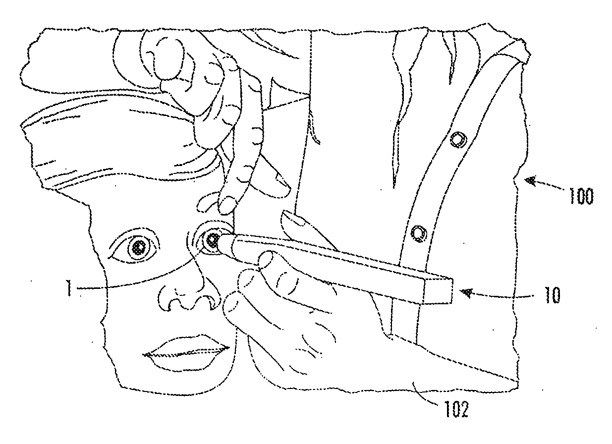
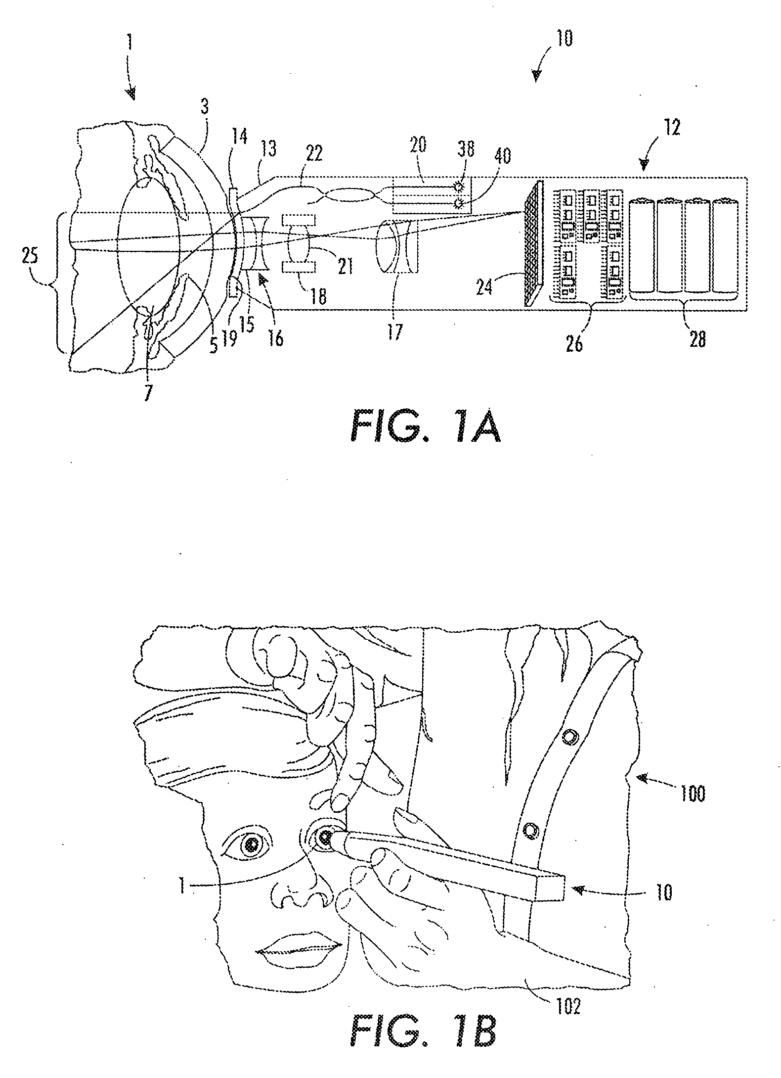
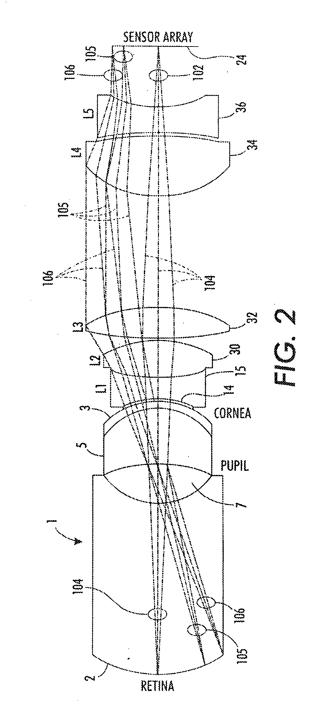
[0056]The retinal imaging system of the i...


PUM


Abstract

A portable hand-held camera for imaging the fundus of an eye, the camera comprising a housing comprising an internal cavity terminating at a forward housing end, a forward lens, and a light source configured to direct light from locations distributed around the perimeter of the forward lens forwardly out of the housing end. In other embodiment, a portable hand-held camera for imaging the fundus of an eye includes optics configured to focus light reflected back from the fundus onto an image receptor, with the optics being capable of varying the field of view among differing portions of the fundus. Methods to ensure unique image identification and storage are described.

Description

CROSS-REFERENCE TO RELATED PATENT APPLICATIONS[0001]This application claims priority from U.S. provisional patent Application No. 61 / 266,564 filed Dec. 4, 2009, the disclosure of which is incorporated herein by reference.STATEMENT REGARDING FEDERALLY SPONSORED RESEARCH OR DEVELOPMENT[0002]This invention was made with United States Government support. The U. S. Government has a paid-up license in this invention and the right under limited circumstances to require the patent owner to license others on reasonable terms as provided for by the terms of Grant No. 1R43EY020714-01 awarded by the National Institutes of Health.TECHNICAL FIELD[0003]This invention relates generally to imaging the back of the eye, and more particularly to a fundus camera for such imaging.BACKGROUND ART[0004]Vision is one of the most valued of human sensory experiences. Vision loss is an often feared untoward health event associated with serious medical, psychological, social, and financial consequences. The pres...

Claims


Application Information

Patent Timeline
Patent Type & Authority Applications(United States)
IPC IPC(8): H04N7/18
CPCA61B3/1208G06K9/00604A61B3/145A61B3/113A61B8/4427G06V40/19
Inventor IGNATOVICH, FILIPP V.KLEINMAN, DAVID M.COTTON, CHRISTOPHER T.BLALOCK, TODD
Owner LUMETRICS
Why Eureka
Try Eureka