Parallel kinematic machine trajectory planning method

a parallel kinematic machine and trajectory planning technology, applied in the field of robotic design and control, can solve the problems of high structural stiffness and rigidity, and the trajectory planning and control system design of pkms is more difficult than serial machines, and achieves the effect of minimizing time and energy

Inactive Publication Date: 2012-11-15
KING FAHD UNIVERSITY OF PETROLEUM AND MINERALS
View PDF9 Cites 67 Cited by
  • Summary
  • Abstract
  • Description
  • Claims
  • Application Information

AI Technical Summary

Benefits of technology

[0007]The parallel kinematic machine trajectory planning method is operable via a data-driven, neuro-fuzzy, multistage-based system. Offline planning based on robot kinematic and dynamic models, including actuators, is performed to generate a large dataset of trajectories covering most of the robot workspace and minimizing time and energy, while avoiding singularities and limits on joint angles, rates, accelerations and torques. The method implements an augmented Lagrangian solver on a decoupled form of the PKM dynamics in order to solve the resulting non-linear constrained optimal control problem. Using outcomes of the offline-planning, the data-driven neuro-fuzzy inference system is built to learn, capture and optimize the desired dynamic behavior of the PKM. The optimized system is used to achieve near-optimal online planning with a reasonable time complexity. The effectiveness of the method is illustrated through a set of simulation experiments proving the technique on a 2-degrees of freedom planar PKM.

Problems solved by technology

This results in high structural stiffness and rigidity.
However, the PKM architecture-dependent performance associated with strong-coupled non-linear dynamics makes the trajectory planning and control system design for PKMs more difficult compared to serial machines.
Another major issue for practical use of PKMs in industry is that for a prescribed tool path in the workspace, the control system should guarantee the prescribed task completion within the workspace, for a given set up of the EE (i.e., for which limitations on actuator lengths and physical dimensions are not violated).

Method used


Image

  • Parallel kinematic machine trajectory planning method
  • Parallel kinematic machine trajectory planning method
  • Parallel kinematic machine trajectory planning method

Examples


Embodiment Construction

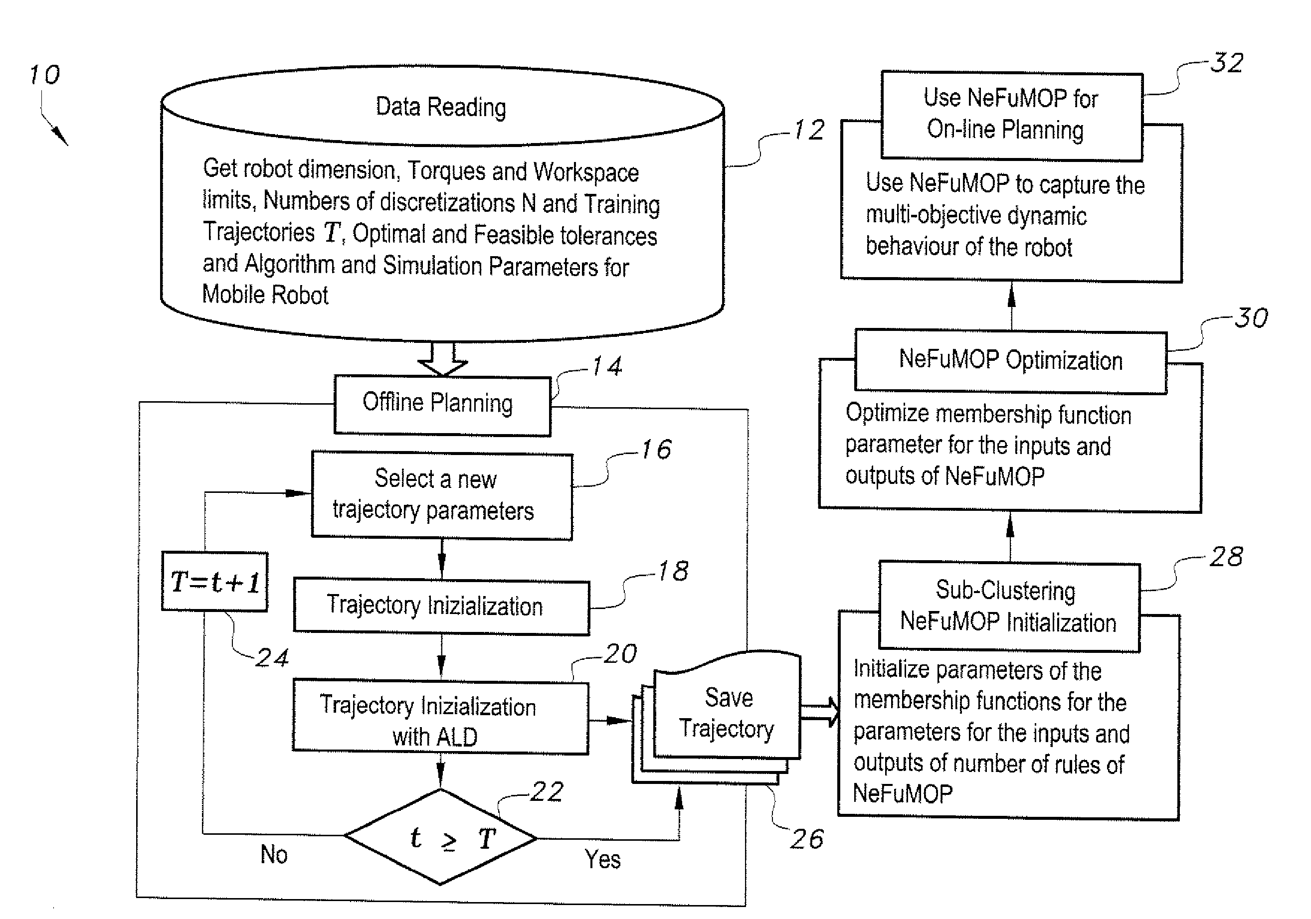
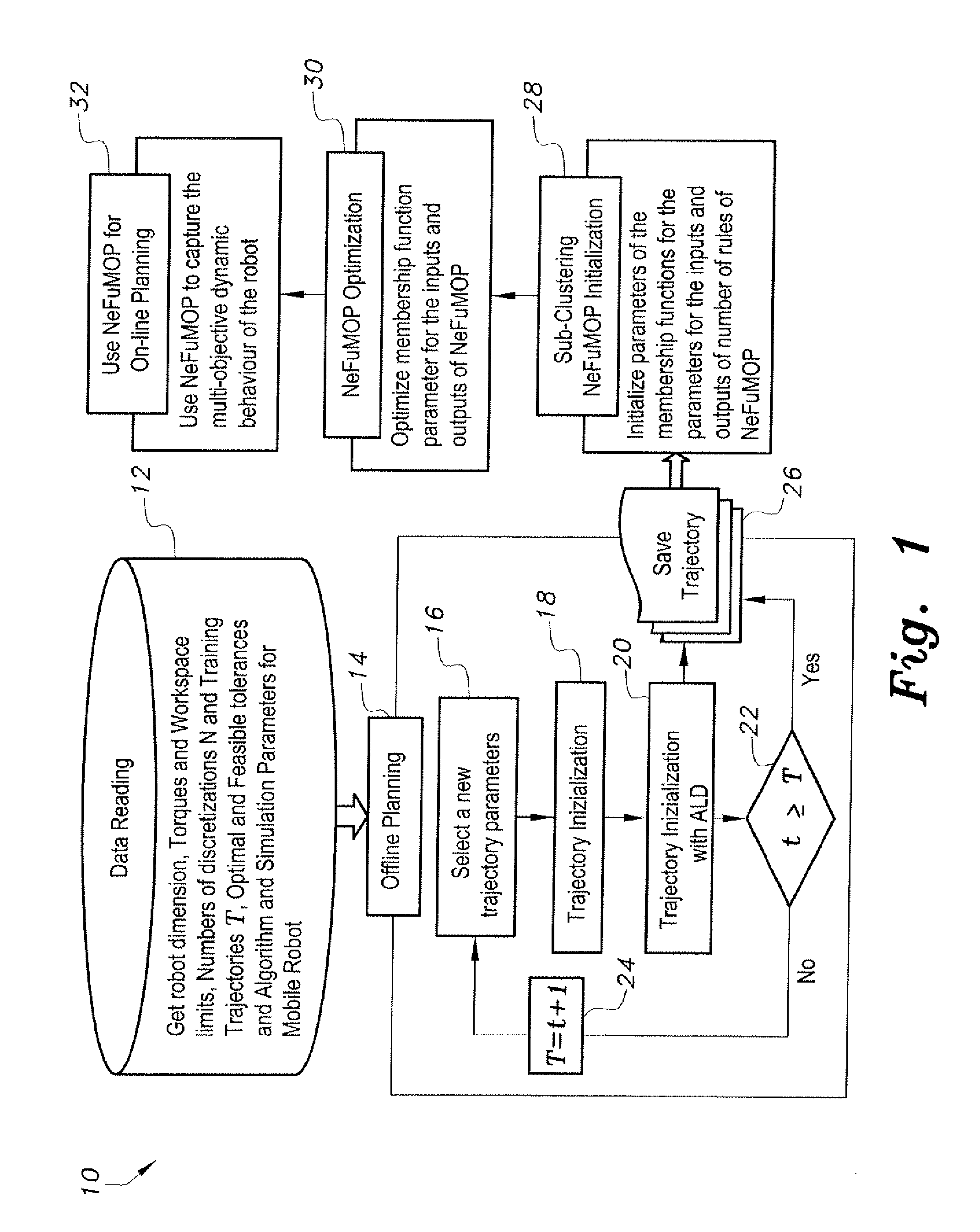
[0041]At the outset, it will be understood that the diagrams in the Figures depicting the parallel kinematic machine trajectory planning method are exemplary only, and may be embodied in a dedicated electronic device having a microprocessor, microcontroller, digital signal processor, application specific integrated circuit, field programmable gate array, any combination of the aforementioned devices, or other device that combines the functionality of the parallel kinematic machine trajectory planning method onto a single chip or multiple chips programmed to carry out the method steps described herein, or may be embodied in a general purpose computer having the appropriate peripherals attached thereto and software stored on non-transitory computer readable media, such as, for example, hard drives, programmable memory chips, floppy disks, USB drives, and the like, that can be loaded into main memory and executed by a processing unit to carry out the functionality and steps of the meth...


PUM


Abstract

The parallel kinematic machine (PKM) trajectory planning method is operable via a data-driven neuro-fuzzy multistage-based system. Offline planning based on robot kinematic and dynamic models, including actuators, is performed to generate a large dataset of trajectories, covering most of the robot workspace and minimizing time and energy, while avoiding singularities and limits on joint angles, rates, accelerations and torques. The method implements an augmented Lagrangian solver on a decoupled form of the PKM dynamics in order to solve the resulting non-linear constrained optimal control problem. Using outcomes of the offline-planning, the data-driven neuro-fuzzy inference system is built to learn, capture to and optimize the desired dynamic behavior of the PKM. The optimized system is used to achieve near-optimal online planning with a reasonable time complexity. The effectiveness of the method is illustrated through a set of simulation experiments proving the technique on a 2-degrees of freedom planar PKM.

Description

BACKGROUND OF THE INVENTION[0001]1. Field of the Invention[0002]The present invention relates generally to robotics design and control, and particularly to a computerized parallel kinematic machine trajectory planning method.[0003]2. Description of the Related Art[0004]Parallel Kinematic Machines (PKMs) have two basic advantages over conventional machines of serial kinematic structures. First, with PKM structures, it is possible to mount all drives on or near the base. This yields to large payloads capability and low inertia. Indeed, the ratio of payload to the robot load is usually about 1 / 10 for serial robots, while only ½ for parallel ones. Second, the connection between the base and the end-effector (EE) is made with several kinematic chains. This results in high structural stiffness and rigidity. However, the PKM architecture-dependent performance associated with strong-coupled non-linear dynamics makes the trajectory planning and control system design for PKMs more difficult c...

Claims


Application Information

Patent Timeline
Patent Type & Authority Applications(United States)
IPC IPC(8): G05B19/18
CPCB25J9/1623G05B2219/40514G05B2219/40466B25J9/1664
Inventor KHOUKHI, AMAR
Owner KING FAHD UNIVERSITY OF PETROLEUM AND MINERALS
Why Eureka
Try Eureka